Spectra
GmbH
&
Co.
KG
vertrieb@spectra.de
User
Manual
‐
Spectra
PowerTwin
P
Apollo
Lake
+
standard Displays
Version
1.0
September
2018
50
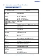
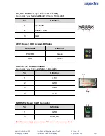
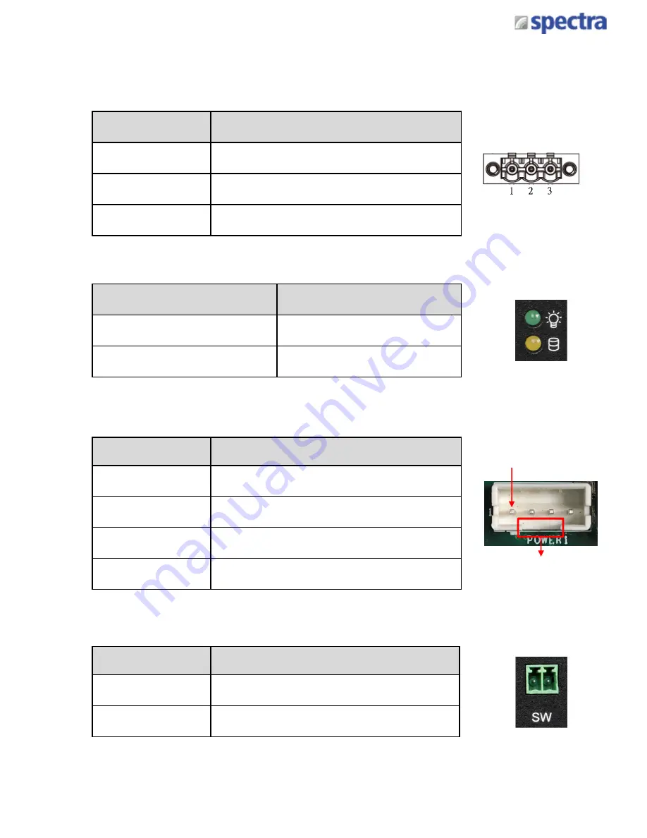
DC_IN1 : DC Power Input Connector (+9~48V)
Connector Type: Terminal Block 1X3 3-pin, 5.0mm pitch
Pin
Definition
1
+9~48VIN
2
Chassis GND
3
GND
POWER1 / 2 : Power Connector
Connector Type: 1x4 4-pin Wafer, 2.0mm pitch
Pin
Definition
1
+5V
2
GND
3
GND
4
+12V
Pin 1
Gap
PWR_SW2: Power On/Off Connector
Pin
Definition
1
GND
2
PWR_SW
(Note:
Please
do
not
apply
power
to
the
pins.
This
port
is
used
to
connect
a
switch.)
1 2
LED1: Power / HDD Access LED Status
LED Status
LED Color
POWER
Green
HDD
Yellow
Summary of Contents for PowerTwin PS12-E3950C9
Page 12: ...Product Introductions Chapter 1...
Page 28: ...System Pin Definitions and Settings Chapter 2...
Page 38: ...System Setup Chapter 3...
Page 56: ...BIOS Setup Chapter 4...
Page 99: ...Product Introductions Chapter 1...
Page 129: ...System Pin Definitions and Settings Chapter 2...
Page 139: ...System Setup Chapter 3...
Page 157: ...BIOS Setup Chapter 4...

