background image

Spectra


GmbH


&


Co.


KG

vertrieb@spectra.de

User


Manual

 ‐

Spectra


PowerTwin


P


Apollo


Lake


+


Sunreadable Displays

Version


1.0

September


2018

21

Environment

• Operating Temperature: -20

°

C to 70

°

(with extended temperature peripherals; Ambient 
with air flow)

• Storage Temperature: -20

°

C to 70

°

C

• Relative Humidity: 90% RH @ 40

°

C (non-

condensing)

• Shock: Operating, 15 Grms, Half-sine 11 ms

Duration (w/ SSD, according to IEC60068-2-27)

• Vibration: Operating, 1.5 Grms, 5-500 Hz, 3 Axes 

(w/ SSD, according to IEC60068-2-64)

• IP Level: IP 65 Compliant Front Panel
• EMC: CE, FCC Class A

Protection

• Reverse Power Input Protection
• Over Voltage Protection: 58V
• Over Current Protection: 15A
• ESD Protection: +/-15kV (air), +/-8kV (contact)
• Surge Protection: 3.84 kV (impedance 12 ohm 

1.2/50

μ

s waveform)

Operating System

• Windows® 10
• Linux: Supports by project

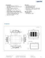
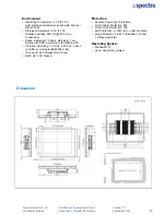
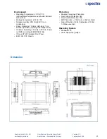
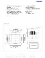
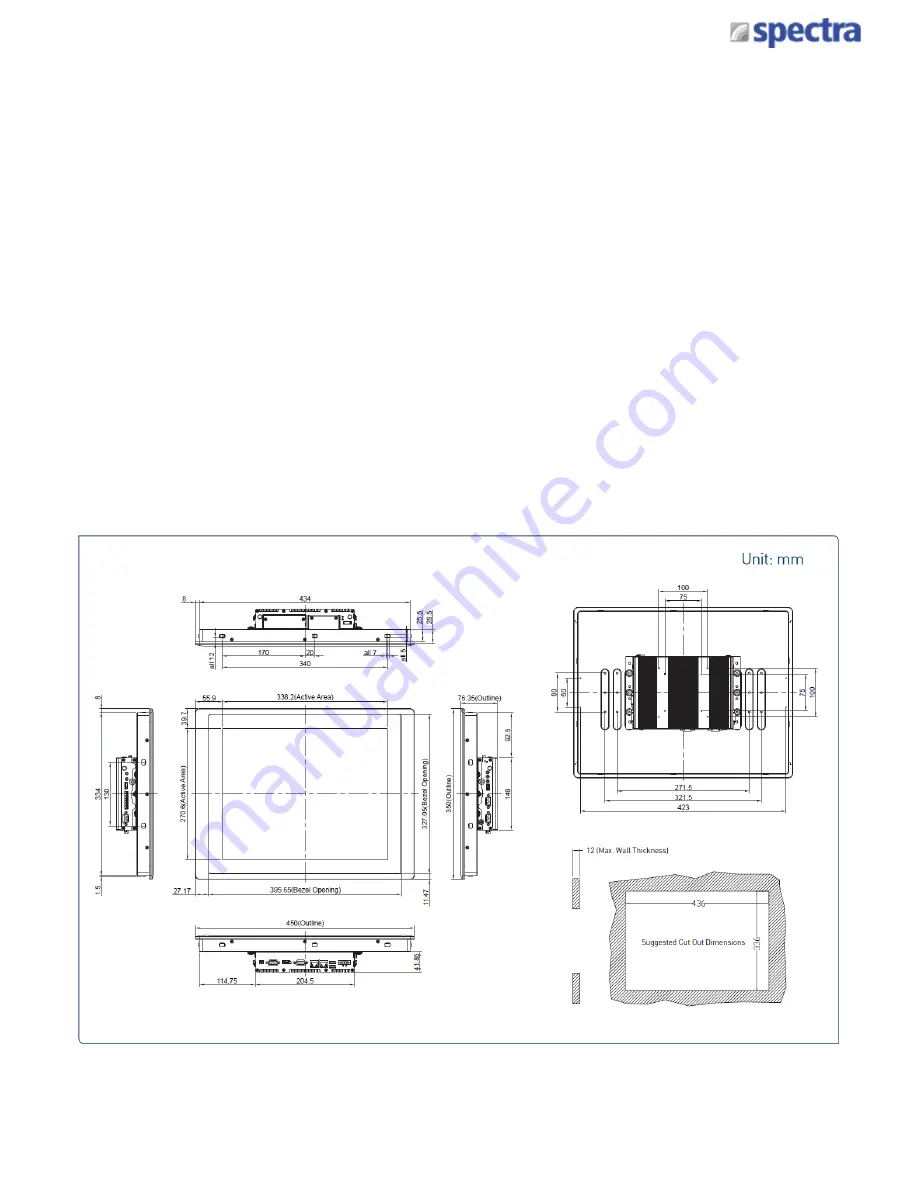
Dimension

Summary of Contents for PowerTwin PS12-E3950C9

Page 1: ...SPECTRA PowerTwin Panel PC E3950 N4200 Apollo Lake with standard Displays USER MANUAL Version 1 0 September 2018...

Page 2: ...SPECTRA PowerTwin Panel PC E3950 N4200 Apollo Lake with sunreadable Displays USER MANUAL Version 1 0 September 2018...

Page 3: ...ctions 1 1 Overview 12 1 2 Highlights 12 1 3 Product Pictures 13 1 4 Key Feature 13 1 5 Hardware Specification 14 1 6 System I O 24 1 6 1 Front 24 1 6 2 Rear 24 1 6 3 Side Left 25 1 6 4 Side Right 25...

Page 4: ...re Monitor 61 4 3 4 S5 RTC Wake Setting 61 4 3 5 Serial Port Console Redirection 62 4 3 6 CPU Configuration 63 4 3 7 Network Stack Configuration 64 4 3 8 CSM Configuration 64 4 3 9 USB Configuration 6...

Page 5: ...t include unintentional technical or typographical errors Changes are periodically made to the information herein to correct such errors and these changes are incorporated into new editions of the pub...

Page 6: ...ou with the most friendly and immediate service RMA Instruction Customers must fill in Spectra Return Merchandise Authorization RMA Request Form and obtain a RMA number prior to returning a defective...

Page 7: ...fore you call Product name and serial number Description of your peripheral attachments Description of your software operating system version application software etc A complete description of the pro...

Page 8: ...oltage and current rating of the cord must be greater than the voltage and current rating marked on the product 9 Position the power cord so that people cannot step on it Do not place anything over th...

Page 9: ...w Pack 1 4 Panel Mounting Kit 1 5 Power Terminal Block Connector 1 6 Remote Power On Off Terminal Block Connector 1 7 DIO Terminal Block Connector 1 8 Thermal Pad for CPU Thermal Block 1 Note Notify y...

Page 10: ...Panel PC with Intel Atom E3950 Quad Core Processor and P Cap Touch Upon Request Spectra PowerTwin with Pentium N4200 CPU Spectra PowerTwin without Touchscreen Model No Product Description Spectra Pow...

Page 11: ...ble 43 x 36 mm PT PN4 CFM PoE02 N 156452 CFM Module with PoE Control Function Individual Port 25 5W N 155629 Adapter AC DC 12V 5A 60W GST60A12 CIN wide temp 30 C 70 C level VI N 155057 Adapter AC DC 2...

Page 12: ...Product Introductions Chapter 1...

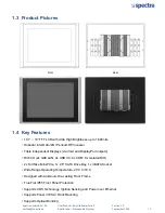
Page 13: ...lso supports Convertible Display System CDS technology Comparing with regular standalone panel PCs it is more flexible and reduces maintenance cost dramatically Featuring with rigorous industrial prot...

Page 14: ...ple Independent Displays via VGA and DisplayPort outputs Rich I O 2x GbE LAN 4x USB 3 0 4x COM 8x Isolated DIO 2x Full Size Mini PCIe 1x 2 5 SATA Drive Bay 1x mSATA Socket Wide Range Operating Tempera...

Page 15: ...mm 1x ATX Power On Off Button 1x Reset Button 1x AT ATX Mode Switch 1x Clear CMOS Switch 1x Remote Power On Off Connector 2 pin Terminal Block 8x Isolated DIO 4x DI 4x DO 10 Pin Terminal Block Storage...

Page 16: ...H 40 C non condensing Shock Operating 15 Grms Half sine 11 ms Duration w SSD according to IEC60068 2 27 Vibration Operating 1 5 Grms 5 500 Hz 3 Axes w SSD according to IEC60068 2 64 IP Level IP 65 Com...

Page 17: ...On Off Button 1x Reset Button 1x AT ATX Mode Switch 1x Clear CMOS Switch 1x Remote Power On Off Connector 2 pin Terminal Block 8x Isolated DIO 4x DI 4x DO 10 Pin Terminal Block Storage 1x 2 5 HDD SSD...

Page 18: ...H 40 C non condensing Shock Operating 15 Grms Half sine 11 ms Duration w SSD according to IEC60068 2 27 Vibration Operating 1 5 Grms 5 500 Hz 3 Axes w SSD according to IEC60068 2 64 IP Level IP 65 Com...

Page 19: ...one Jack 3 5mm 1x ATX Power On Off Button 1x Reset Button 1x AT ATX Mode Switch 1x Clear CMOS Switch 1x Remote Power On Off Connector 2 pin Terminal Block 8x Isolated DIO 4x DI 4x DO 10 Pin Terminal B...

Page 20: ...H 40 C non condensing Shock Operating 15 Grms Half sine 11 ms Duration w SSD according to IEC60068 2 27 Vibration Operating 1 5 Grms 5 500 Hz 3 Axes w SSD according to IEC60068 2 64 IP Level IP 65 Com...

Page 21: ...hone Jack 3 5mm 1x ATX Power On Off Button 1x Reset Button 1x AT ATX Mode Switch 1x Clear CMOS Switch 1x Remote Power On Off Connector 2 pin Terminal Block 8x Isolated DIO 4x DI 4x DO 10 Pin Terminal...

Page 22: ...H 40 C non condensing Shock Operating 15 Grms Half sine 11 ms Duration w SSD according to IEC60068 2 27 Vibration Operating 1 5 Grms 5 500 Hz 3 Axes w SSD according to IEC60068 2 64 IP Level IP 65 Com...

Page 23: ...hone Jack 3 5mm 1x ATX Power On Off Button 1x Reset Button 1x AT ATX Mode Switch 1x Clear CMOS Switch 1x Remote Power On Off Connector 2 pin Terminal Block 8x Isolated DIO 4x DI 4x DO 10 Pin Terminal...

Page 24: ...H 40 C non condensing Shock Operating 15 Grms Half sine 11 ms Duration w SSD according to IEC60068 2 27 Vibration Operating 1 5 Grms 5 500 Hz 3 Axes w SSD according to IEC60068 2 64 IP Level IP 65 Com...

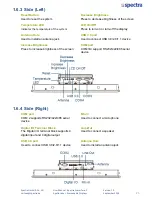
Page 25: ...itor Display Port Used to connect the system with DisplayPort monitor COM port COM 1 supports RS232 422 485 serial device Remote Power On Off Terminal Block Used to plug a remote power on off terminal...

Page 26: ...Press to decrease brightness of the screen LCD On Off Press to turn on or turn off the display USB 3 0 port Used to connect USB 3 0 2 0 1 1 device COM port COM 3 4 support RS232 422 485 serial device...

Page 27: ...Co KG vertrieb spectra de User Manual Spectra PowerTwin P Apollo Lake Sunreadable Displays Version 1 0 September 2018 26 VESA Mounting Hole These are mounting holes for VESA mount 75x75mm and 100x100...

Page 28: ...System Pin Definitions and Settings Chapter 2...

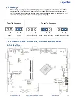
Page 29: ...jumper cap is placed on both pins the jumper is short If you remove the jumper cap or place the jumper cap on just one pin the jumper is open Refer to below for examples of the 2 pin and 3 pin jumper...

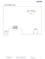
Page 30: ...Spectra GmbH Co KG vertrieb spectra de User Manual Spectra PowerTwin P Apollo Lake Sunreadable Displays Version 1 0 September 2018 29 2 2 2 Bottom View...

Page 31: ...Ports COM1_1 COM2_1 COM3_1 COM4_1 RS232 RS422 RS485 Connector DC_IN1 3 pin DC 9 48V Power Input with Power Ignition Connector LAN1 LAN Connector LAN2 LAN Connector VGA1 VGA Connector DP1 DisplayPort...

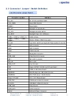
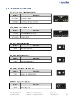
Page 32: ...on of Switches AT_ATX AT ATX Power Mode Switch CLR_CMOS Clear CMOS Switch Switch Definition 1 2 Left Normal Status Default 2 3 Right Clear CMOS BL_UP1 Backlight Increase Switch Definition Push Backlig...

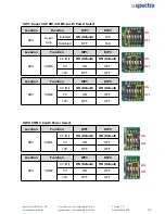
Page 33: ...t N A Disabled OFF N A Location Function DIP3 DIP4 SW1 COM3 0V RI ON Default ON Default 5V ON OFF 12V OFF OFF ON OFF ON OFF Location Function DIP5 DIP6 SW1 COM4 0V RI ON Default ON Default 5V ON OFF 1...

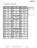
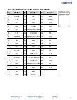
Page 34: ...AKE 19 NA 37 RESERVED 2 3 3V 20 3 3V 38 USB_D 3 NA 21 GND 39 RESERVED 4 GND 22 PERST 40 GND 5 NA 23 PERN0 USB3RN0 SATARP0 41 3 3V 6 1 5V 24 3 3V 42 NA 7 CLKREQ 25 PERP0 USB3RP0 SATARN0 43 GND 8 SIM_VC...

Page 35: ...efinition 1 WAKE 19 NA 37 GND 2 3 3V 20 3 3V 38 USB_D 3 NA 21 GND 39 3 3V 4 GND 22 PERST 40 GND 5 NA 23 PERN0 SATARP0 41 3 3V 6 1 5V 24 3 3VAUX 42 NA 7 CLKREQ 25 PERP0 SATARN0 43 GND 8 NA 26 GND 44 NA...

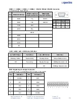
Page 36: ...R RX 5 GND 6 DSR 7 RTS 8 CTS 9 RI Power over Serial PIN Definitions Pin RS232 RS422 485 RS485 5 GND GND GND 9 0 5 12V 0 5 12V 0 5 12V LAN1 LAN2 LAN LED Status Definition Act LED Status Definition Link...

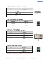
Page 37: ...3 3 pin 5 0mm pitch Pin Definition 1 9 48VIN 2 Chassis GND 3 GND POWER1 2 Power Connector Connector Type 1x4 4 pin Wafer 2 0mm pitch Pin Definition 1 5V 2 GND 3 GND 4 12V Pin 1 Gap PWR_SW2 Power On Of...

Page 38: ...System Setup Chapter 3...

Page 39: ...2018 38 3 1 Removing the Top Cover In order to prevent electric shock or system damage before removing the chassis cover must turn off power and disconnect the unit from power source WARNING 1 Loosen...

Page 40: ...September 2018 39 3 2 Installing a Half Size Mini PCIe Card 1 Locate the Mini PCIe slot 2 Use provided two screws on bracket to fasten the module and bracket together 3 Tilt the Mini PCIe module at 4...

Page 41: ...ion 1 0 September 2018 40 4 Press down the module and use the two screws to fix the module 3 3 Installing a Full Size Mini PCIe Card 1 Locate the Mini PCIe slot 2 Tilt the Mini PCIe module at 45 degre...

Page 42: ...PowerTwin P Apollo Lake Sunreadable Displays Version 1 0 September 2018 41 3 Press down the module and use the two screws to fix the module 3 4 Installing Antennas 1 Remove the antenna hole covers at...

Page 43: ...Spectra PowerTwin P Apollo Lake Sunreadable Displays Version 1 0 September 2018 42 3 Put on washer and fasten the nut with antenna jack 4 Assemble the antenna and antenna jack together 5 Attach the RF...

Page 44: ...1 0 September 2018 43 3 5 Installing a SO DIMM 1 Locate SO DIMM socket 2 Tilt the SODIMM module at a 45 degree angle and insert it to SODIMM socket until the gold pated connector of module contacted f...

Page 45: ...al Spectra PowerTwin P Apollo Lake Sunreadable Displays Version 1 0 September 2018 44 3 6 Installing CPU Thermal Pad 1 Place the thermal pad on the CPU heatsink 3 7 Installing the Top Cover 1 Put on t...

Page 46: ...ual Spectra PowerTwin P Apollo Lake Sunreadable Displays Version 1 0 September 2018 45 3 8 Installing a SATA Hard Drive 1 Loosen 2 screws on front panel to remove cover plate 2 Turn over the unit to h...

Page 47: ...out the HDD bracket 4 Make the bottom side of the HDD face up place the HDD bracket on it Ensure the direction of bracket is correct and use 4 provided screws to assemble HDD and HDD bracket together...

Page 48: ...Manual Spectra PowerTwin P Apollo Lake Sunreadable Displays Version 1 0 September 2018 47 3 9 Installing a SIM Card 3 Insert the SIM card 1 Loosen 2 screws on front panel to remove cover plate 2 SIM c...

Page 49: ...lays Version 1 0 September 2018 48 3 10 Connecting with Display Module 1 Locate the module connector slot 2 Turn over the unit to have the bottom side face up loosen the 2 screws of the module connect...

Page 50: ...bH Co KG vertrieb spectra de User Manual Spectra PowerTwin P Apollo Lake Sunreadable Displays Version 1 0 September 2018 49 3 Connect the module 4 Fasten the 6 screws to fix the PC module on the displ...

Page 51: ...indicates VESA mounting hole pattern on PE3950 N4200series which is compliant with VESA mounting standard 1 The following picture uses a panel PC PE3950 N4200 Module display module as a demonstration...

Page 52: ...in P Apollo Lake Sunreadable Displays Version 1 0 September 2018 3 12 Panel Mount Accessories provided are as follows Mounting Kits Panel Mount PPC Before assembly please prepare panel mount PPC and c...

Page 53: ...pollo Lake Sunreadable Displays Version 1 0 September 2018 2 All mounting kits displayed are to be inserted intoholes 3 Installation preparation and steps Before Mounting Kits are installed Panel moun...

Page 54: ...spectra de User Manual Spectra PowerTwin P Apollo Lake Sunreadable Displays Version 1 0 September 2018 Position panel mount kits Insert the panel mounting kit into bottom hole Slide the kit toward ba...

Page 55: ...rTwin P Apollo Lake Sunreadable Displays Version 1 0 September 2018 4 Apply all mount kits to the rest of holes And you have completed the panel mount installation as shown below STEP 4 Tighten the sc...

Page 56: ...BIOS Setup Chapter 4...

Page 57: ...keys Control Keys Move to select screen Move to select item Esc Quit the BIOS Setup Enter Select item Page Up Increases the numeric value or makes changes Page Down Decreases the numeric value or make...

Page 58: ...in Setup Press Del key to enter BIOS CMOS Setup Utility the Main Menu as shown below will appears on the screen Use arrow keys to move among the items and press Enter to accept or enter a sub menu Sys...

Page 59: ...ctra PowerTwin P Apollo Lake Sunreadable Displays Version 1 0 September 2018 58 4 3 Advanced Setup This section allows you to configure and improve your system and allows you to set up some system fea...

Page 60: ...This option may not be effective with some OS ACPI Sleep State S3 Suspend to RAM Allows users to select the highest Advanced Configuration Power Interface ACPI sleep state that system will enter when...

Page 61: ...Port 1 4 Mode RS232 Allows you to select Serial Port Mode Configuration options RS232 RS422 RS485 Full Duplex RS485 Half Duplex Watch Dog Function You can setup the system watch dog timer a hardware t...

Page 62: ...PowerTwin P Apollo Lake Sunreadable Displays Version 1 0 September 2018 61 4 3 3 Hardware Monitor This screen displays the current status of all monitored hardware devices components such as voltages...

Page 63: ...r disables wake system from S5 soft off state Disabled Disables wake system from S5 Fixed Time Sets a fixed time HH MM SS to wake system from S5 Dynamic Time Sets a increase minute s from current time...

Page 64: ...memory Active Processor Cores Allows you to choose the number of active processor cores Configuration options All 1 Intel Virtualization Technology Enabled Enables or disables Intel Virtualization Te...

Page 65: ...Spectra PowerTwin P Apollo Lake Sunreadable Displays Version 1 0 September 2018 64 4 3 7 Network Stack Configuration Network Stack Disabled Enables or disables UEFI Network Stack 4 3 8 CSM Configurat...

Page 66: ...I option ROM Network PXE Do not launch Controls the execution of UEFI and Legacy PXE Network Preboot eXecution Environment option ROM Do not launch Disables option ROM execution UEFI Enables UEFI opti...

Page 67: ...lows you to enable or disable legacy USB support When set to Auto legacy USB support will be disabled automatically if no USB devices are connected XHCI Hand off Enabled Enables or disables XHCI USB3...

Page 68: ...le Displays Version 1 0 September 2018 67 4 4 Chipset Setup This section allows you to configure chipset related settings according to user s preference 4 4 1 North Bridge This section provides inform...

Page 69: ...ting System version to install Configuration options Windows Intel Linux Mini PCIE2 mSATA Switch Mini PCIE Allows you to change Mini PCIE2 as Mini PCIE or mSATA Amplifier Function Enabled Enables or d...

Page 70: ...Spectra GmbH Co KG vertrieb spectra de User Manual Spectra PowerTwin P Apollo Lake Sunreadable Displays Version 1 0 September 2018 69 4 4 3 South Cluster Configuration PCI Express Configuration...

Page 71: ...ort PCIeSpeed Auto Allows you to select PCI Express port speed Configuration options Auto Gen1 Gen2 PCI Express Root Port 6 MiniPcie PCI Express Root Port 6 MiniPcie Enabled Enables or disables PCI Ex...

Page 72: ...r state system will enter when power is resumed after a power failure G3 state Always on Enters to power on state Always off Enters to power off state Last state Enters to the last power state before...

Page 73: ...ptember 2018 72 4 5 Security Setup This section allows you to configure BIOS security settings Administrator Password Allows you to set Administrator Password to control access to the BIOS Setup utili...

Page 74: ...NumLock State Allows you to set NumLock key to On or Off state when system boots up Quiet Boot Allows you to enable or disable Quiet Boot function Fast Boot Allows you to enable or disable Fast Boot...

Page 75: ...ystem after saving changes Discard Changes and Reset This item allows you to reset system setup without saving any changes Restore Defaults This item allows you to restore load default values for all...

Page 76: ...Spectra GmbH Co KG vertrieb spectra de User Manual Spectra PowerTwin P Apollo Lake Sunreadable Displays Version 1 0 September 2018 Product Application Chapter 5...

Page 77: ...ram the Super I O chip F81866A configuration registers the following configuration procedures must be followed in sequence 1 Enter the Extended Function Mode 2 Configure the configuration registers 3...

Page 78: ...eb spectra de User Manual Spectra PowerTwin P Apollo Lake Sunreadable Displays Version 1 0 September 2018 77 5 1 1 3 Relative Registers To program the F81866A configuration registers see the following...

Page 79: ...Byte AddrPort 0x87 Must write twice to enter Extended mode Select Logic Device WriteByte AddrPort 0x07 WriteByte dataPort 0x06 Select logic device 06h Input Mode Selection Set GP74 to GP77 input Mode...

Page 80: ...te twice to enter Extended mode Select Logic Device WriteByte AddrPort 0x07 WriteByte DataPort 0x06 Select logic device 06h Output Mode Selection Set GP80 to GP83 output Mode WriteByte AddrPort 0x88 S...

Page 81: ...0x61 Select configuration register 61h Low Byte address WriteByte DataPort 0x00 Leave the Extended Function Mode WriteByte AddrPort 0xAA Note DIO Port base address is 0x0A00h 5 1 1 6 DATA Bit Table D...

Page 82: ...tion XCOM Isolated power in V XCOM Isolated power in V Isolated power in DC voltage 5 48V 4 x Digital Input Source Type Input Signal Voltage Level Signal Logic 0 XCOM 5V Signal Low V 0 4V XCOM 5V V Si...

Page 83: ...PowerTwin P Apollo Lake Sunreadable Displays Version 1 0 September 2018 82 DIO1 Digital Input Output Connector Connector Type Terminal Block 1X10 10 pin 3 5mm pitch Pin Definition Pin Definition 1 XC...

Page 84: ...Spectra GmbH Co KG vertrieb spectra de User Manual Spectra PowerTwin P Apollo Lake Sunreadable Displays Version 1 0 September 2018 Optional Module Pin Definitions and Settings Chapter 6...

Page 85: ...tion Sensing Control Function 12V 24V Selectable CFM PoE CFM Module with PoE Control Function Individual Port 25 5W 84 6 1 Location of the Connectors and Switches 6 2 Installing a CFM IGN Power Igniti...

Page 86: ...n 1 2 24V Car Battery Input 2 3 12V Car Battery Input 24V_12V_1 12V 24V Car Battery Switch Pin 1 Pin 2 Pin 3 Pin 4 Definition OFF ON ON ON ON 0 second ON ON OFF 1 minute ON OFF ON 5 minutes ON OFF OFF...

Page 87: ...ersion 1 0 September 2018 86 6 3 Installing a CFM PoE Control Module 1 Locate the PoE connector on system motherboard as indicated 2 Insert the female connector of CFM PoE module to the male connector...

Page 88: ...ser Manual Spectra PowerTwin P Apollo Lake Sunreadable Displays Version 1 0 September 2018 87 4 Paste the heatsink onto the CFM PoE module carefully and fasten 2 screws to fix it 5 Paste the thermal p...

Page 89: ...ell Wels Austria 43 0 7240 20190 info spectra austria at www spectra austria at Phone E Mail Web Spectra Schweiz AG Flugplatzstr 5 8404 Winterthur Switzerland 41 0 43 2771050 info spectra ch www spect...

Page 90: ...Contents 08 Ordering Information 09 Optional Accessories and Modules 10 Chapter 1 Product Introductions 1 1 Overview 12 1 2 Highlights 12 1 3 Product Pictures 13 1 4 Key Feature 13 1 5 Hardware Speci...

Page 91: ...3 Advanced Setup 72 4 3 1 ACPI Settings 72 4 3 2 F81866 Super IO Configuration 73 4 3 3 Hardware Monitor 75 4 3 4 S5 RTC Wake Setting 75 4 3 5 Serial Port Console Redirection 76 4 3 6 CPU Configurati...

Page 92: ...include unintentional technical or typographical errors Changes are periodically made to the information herein to correct such errors and these changes are incorporated into new editions of the publ...

Page 93: ...u with the most friendly and immediate service RMA Instruction Customers must fill in Spectra Return Merchandise Authorization RMA Request Form and obtain a RMA number prior to returning a defective p...

Page 94: ...ore you call Product name and serial number Description of your peripheral attachments Description of your software operating system version application software etc A complete description of the prob...

Page 95: ...tage and current rating of the cord must be greater than the voltage and current rating marked on the product 9 Position the power cord so that people cannot step on it Do not place anything over the...

Page 96: ...Pack 1 4 Panel Mounting Kit 1 5 Power Terminal Block Connector 1 6 Remote Power On Off Terminal Block Connector 1 7 DIO Terminal Block Connector 1 8 Thermal Pad for CPU Thermal Block 1 Note Notify yo...

Page 97: ...Panel PC with Intel Atom E3950 Quad Core Processor and P Cap Touch Spectra PowerTwin P15 E3950R9 S 15 TFT LCD XGA 4 3 Modular Touch Panel PC with Intel Atom E3950 Quad Core Processor and Resistive 5 w...

Page 98: ...ith Power Ignition Sensing Control Function 12V 24V Selectable 43 x 36 mm PT PN4 CFM PoE02 N 156452 CFM Module with PoE Control Function Individual Port 25 5W N 155629 Adapter AC DC 12V 5A 60W GST60A1...

Page 99: ...Product Introductions Chapter 1...

Page 100: ...orts Convertible Display System CDS technology Comparing with regular standalone panel PCs it is more flexible and reduces maintenance cost dramatically Featuring with rigorous industrial protections...

Page 101: ...Onboard Intel Atom Pentium Processor Triple Independent Displays via VGA and DisplayPort outputs Rich I O 2x GbE LAN 4x USB 3 0 4x COM 8x Isolated DIO 2x Full Size Mini PCIe 1x 2 5 SATA Drive Bay 1x m...

Page 102: ...ic in Phone Jack 3 5mm 1x ATX Power On Off Button 1x Reset Button 1x AT ATX Mode Switch 1x Clear CMOS Switch 1x Remote Power On Off Connector 2 pin Terminal Block 8x Isolated DIO 4x DI 4x DO 10 Pin Te...

Page 103: ...0 C non condensing Shock Operating 15 Grms Half sine 11 ms Duration w SSD according to IEC60068 2 27 Vibration Operating 1 5 Grms 5 500 Hz 3 Axes w SSD according to IEC60068 2 64 IP Level IP 65 Compli...

Page 104: ...Supports 5V 12V DB9 1x Speaker out 1x Mic in Phone Jack 3 5mm 1x ATX Power On Off Button 1x Reset Button 1x AT ATX Mode Switch 1x Clear CMOS Switch 1x Remote Power On Off Connector 2 pin Terminal Blo...

Page 105: ...ty 95 RH 40 C non condensing Shock Operating 15 Grms Half sine 11 ms Duration w SSD according to IEC60068 2 27 Vibration Operating 1 5 Grms 5 500 Hz 3 Axes w SSD according to IEC60068 2 64 IP Level IP...

Page 106: ...upports 5V 12V DB9 1x Speaker out 1x Mic in Phone Jack 3 5mm 1x ATX Power On Off Button 1x Reset Button 1x AT ATX Mode Switch 1x Clear CMOS Switch 1x Remote Power On Off Connector 2 pin Terminal Block...

Page 107: ...ty 90 RH 40 C non condensing Shock Operating 15 Grms Half sine 11 ms Duration w SSD according to IEC60068 2 27 Vibration Operating 1 5 Grms 5 500 Hz 3 Axes w SSD according to IEC60068 2 64 IP Level IP...

Page 108: ...pports 5V 12V DB9 1x Speaker out 1x Mic in Phone Jack 3 5mm 1x ATX Power On Off Button 1x Reset Button 1x AT ATX Mode Switch 1x Clear CMOS Switch 1x Remote Power On Off Connector 2 pin Terminal Block...

Page 109: ...ty 90 RH 40 C non condensing Shock Operating 15 Grms Half sine 11 ms Duration w SSD according to IEC60068 2 27 Vibration Operating 1 5 Grms 5 500 Hz 3 Axes w SSD according to IEC60068 2 64 IP Level IP...

Page 110: ...pports 5V 12V DB9 1x Speaker out 1x Mic in Phone Jack 3 5mm 1x ATX Power On Off Button 1x Reset Button 1x AT ATX Mode Switch 1x Clear CMOS Switch 1x Remote Power On Off Connector 2 pin Terminal Block...

Page 111: ...y 80 RH 50 C non condensing Shock Operating 15 Grms Half sine 11 ms Duration w SSD according to IEC60068 2 27 Vibration Operating 1 5 Grms 5 500 Hz 3 Axes w SSD according to IEC60068 2 64 IP Level IP...

Page 112: ...Supports 5V 12V DB9 1x Speaker out 1x Mic in Phone Jack 3 5mm 1x ATX Power On Off Button 1x Reset Button 1x AT ATX Mode Switch 1x Clear CMOS Switch 1x Remote Power On Off Connector 2 pin Terminal Bloc...

Page 113: ...ty 80 RH 50 C non condensing Shock Operating 15 Grms Half sine 11 ms Duration w SSD according to IEC60068 2 27 Vibration Operating 1 5 Grms 5 500 Hz 3 Axes w SSD according to IEC60068 2 64 IP Level IP...

Page 114: ...x ATX Power On Off Button 1x Reset Button 1x AT ATX Mode Switch 1x Clear CMOS Switch 1x Remote Power On Off Connector 2 pin Terminal Block 8x Isolated DIO 4x DI 4x DO 10 Pin Terminal Block Storage 1x...

Page 115: ...ty 80 RH 50 C non condensing Shock Operating 15 Grms Half sine 11 ms Duration w SSD according to IEC60068 2 27 Vibration Operating 1 5 Grms 5 500 Hz 3 Axes w SSD according to IEC60068 2 64 IP Level IP...

Page 116: ...upports 5V 12V DB9 1x Speaker out 1x Mic in Phone Jack 3 5mm 1x ATX Power On Off Button 1x Reset Button 1x AT ATX Mode Switch 1x Clear CMOS Switch 1x Remote Power On Off Connector 2 pin Terminal Block...

Page 117: ...50 C non condensing Shock Operating 15 Grms Half sine 11 ms Duration w SSD according to IEC60068 2 27 Vibration Operating 1 5 Grms 5 500 Hz 3 Axes w SSD according to IEC60068 2 64 IP Level IP 65 Compl...

Page 118: ...ATX Power On Off Button 1x Reset Button 1x AT ATX Mode Switch 1x Clear CMOS Switch 1x Remote Power On Off Connector 2 pin Terminal Block 8x Isolated DIO 4x DI 4x DO 10 Pin Terminal Block Storage 1x 2...

Page 119: ...50 C non condensing Shock Operating 15 Grms Half sine 11 ms Duration w SSD according to IEC60068 2 27 Vibration Operating 1 5 Grms 5 500 Hz 3 Axes w SSD according to IEC60068 2 64 IP Level IP 65 Compl...

Page 120: ...Supports 5V 12V DB9 1x Speaker out 1x Mic in Phone Jack 3 5mm 1x ATX Power On Off Button 1x Reset Button 1x AT ATX Mode Switch 1x Clear CMOS Switch 1x Remote Power On Off Connector 2 pin Terminal Blo...

Page 121: ...y 80 RH 50 C non condensing Shock Operating 15 Grms Half sine 11 ms Duration w SSD according to IEC60068 2 27 Vibration Operating 1 5 Grms 5 500 Hz 3 Axes w SSD according to IEC60068 2 64 IP Level IP...

Page 122: ...ol Supports 5V 12V DB9 1x Speaker out 1x Mic in Phone Jack 3 5mm 1x ATX Power On Off Button 1x Reset Button 1x AT ATX Mode Switch 1x Clear CMOS Switch 1x Remote Power On Off Connector 2 pin Terminal B...

Page 123: ...y 80 RH 50 C non condensing Shock Operating 15 Grms Half sine 11 ms Duration w SSD according to IEC60068 2 27 Vibration Operating 1 5 Grms 5 500 Hz 3 Axes w SSD according to IEC60068 2 64 IP Level IP...

Page 124: ...1x ATX Power On Off Button 1x Reset Button 1x AT ATX Mode Switch 1x Clear CMOS Switch 1x Remote Power On Off Connector 2 pin Terminal Block 8x Isolated DIO 4x DI 4x DO 10 Pin Terminal Block Storage 1...

Page 125: ...y 80 RH 50 C non condensing Shock Operating 15 Grms Half sine 11 ms Duration w SSD according to IEC60068 2 27 Vibration Operating 1 5 Grms 5 500 Hz 3 Axes w SSD according to IEC60068 2 64 IP Level IP...

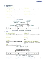
Page 126: ...or Display Port Used to connect the system with DisplayPort monitor COM port COM 1 supports RS232 422 485 serial device Remote Power On Off Terminal Block Used to plug a remote power on off terminal b...

Page 127: ...ess to decrease brightness of the screen LCD On Off Press to turn on or turn off the display USB 3 0 port Used to connect USB 3 0 2 0 1 1 device COM port COM 3 4 support RS232 422 485 serial device CO...

Page 128: ...H Co KG vertrieb spectra de User Manual Spectra PowerTwin P Apollo Lake standard Displays Version 1 0 September 2018 40 VESA Mounting Hole These are mounting holes for VESA mount 75x75mm and 100x100mm...

Page 129: ...System Pin Definitions and Settings Chapter 2...

Page 130: ...umper cap is placed on both pins the jumper is short If you remove the jumper cap or place the jumper cap on just one pin the jumper is open Refer to below for examples of the 2 pin and 3 pin jumpers...

Page 131: ...Spectra GmbH Co KG vertrieb spectra de User Manual Spectra PowerTwin P Apollo Lake standard Displays Version 1 0 September 2018 43 2 2 2 Bottom View...

Page 132: ...orts COM1_1 COM2_1 COM3_1 COM4_1 RS232 RS422 RS485 Connector DC_IN1 3 pin DC 9 48V Power Input with Power Ignition Connector LAN1 LAN Connector LAN2 LAN Connector VGA1 VGA Connector DP1 DisplayPort Co...

Page 133: ...n of Switches AT_ATX AT ATX Power Mode Switch CLR_CMOS Clear CMOS Switch Switch Definition 1 2 Left Normal Status Default 2 3 Right Clear CMOS BL_UP1 Backlight Increase Switch Definition Push Backligh...

Page 134: ...N A Disabled OFF N A Location Function DIP3 DIP4 SW1 COM3 0V RI ON Default ON Default 5V ON OFF 12V OFF OFF ON OFF ON OFF Location Function DIP5 DIP6 SW1 COM4 0V RI ON Default ON Default 5V ON OFF 12...

Page 135: ...E 19 NA 37 RESERVED 2 3 3V 20 3 3V 38 USB_D 3 NA 21 GND 39 RESERVED 4 GND 22 PERST 40 GND 5 NA 23 PERN0 USB3RN0 SATARP0 41 3 3V 6 1 5V 24 3 3V 42 NA 7 CLKREQ 25 PERP0 USB3RP0 SATARN0 43 GND 8 SIM_VCC...

Page 136: ...finition 1 WAKE 19 NA 37 GND 2 3 3V 20 3 3V 38 USB_D 3 NA 21 GND 39 3 3V 4 GND 22 PERST 40 GND 5 NA 23 PERN0 SATARP0 41 3 3V 6 1 5V 24 3 3VAUX 42 NA 7 CLKREQ 25 PERP0 SATARN0 43 GND 8 NA 26 GND 44 NA...

Page 137: ...RX 5 GND 6 DSR 7 RTS 8 CTS 9 RI Power over Serial PIN Definitions Pin RS232 RS422 485 RS485 5 GND GND GND 9 0 5 12V 0 5 12V 0 5 12V LAN1 LAN2 LAN LED Status Definition Act LED Status Definition Link...

Page 138: ...3 pin 5 0mm pitch Pin Definition 1 9 48VIN 2 Chassis GND 3 GND POWER1 2 Power Connector Connector Type 1x4 4 pin Wafer 2 0mm pitch Pin Definition 1 5V 2 GND 3 GND 4 12V Pin 1 Gap PWR_SW2 Power On Off...

Page 139: ...System Setup Chapter 3...

Page 140: ...2018 52 3 1 Removing the Top Cover In order to prevent electric shock or system damage before removing the chassis cover must turn off power and disconnect the unit from power source WARNING 1 Loosen...

Page 141: ...eptember 2018 53 3 2 Installing a Half Size Mini PCIe Card 1 Locate the Mini PCIe slot 2 Use provided two screws on bracket to fasten the module and bracket together 3 Tilt the Mini PCIe module at 45...

Page 142: ...n 1 0 September 2018 54 4 Press down the module and use the two screws to fix the module 3 3 Installing a Full Size Mini PCIe Card 1 Locate the Mini PCIe slot 2 Tilt the Mini PCIe module at 45 degree...

Page 143: ...a PowerTwin P Apollo Lake standard Displays Version 1 0 September 2018 55 3 Press down the module and use the two screws to fix the module 3 4 Installing Antennas 1 Remove the antenna hole covers at f...

Page 144: ...l Spectra PowerTwin P Apollo Lake standard Displays Version 1 0 September 2018 56 3 Put on washer and fasten the nut with antenna jack 4 Assemble the antenna and antenna jack together 5 Attach the RF...

Page 145: ...0 September 2018 57 3 5 Installing a SO DIMM 1 Locate SO DIMM socket 2 Tilt the SODIMM module at a 45 degree angle and insert it to SODIMM socket until the gold pated connector of module contacted fi...

Page 146: ...nual Spectra PowerTwin P Apollo Lake standard Displays Version 1 0 September 2018 58 3 6 Installing CPU Thermal Pad 1 Place the thermal pad on the CPU heatsink 3 7 Installing the Top Cover 1 Put on th...

Page 147: ...anual Spectra PowerTwin P Apollo Lake standard Displays Version 1 0 September 2018 59 3 8 Installing a SATA Hard Drive 1 Loosen 2 screws on front panel to remove cover plate 2 Turn over the unit to ha...

Page 148: ...ut the HDD bracket 4 Make the bottom side of the HDD face up place the HDD bracket on it Ensure the direction of bracket is correct and use 4 provided screws to assemble HDD and HDD bracket together 5...

Page 149: ...Manual Spectra PowerTwin P Apollo Lake standard Displays Version 1 0 September 2018 61 3 9 Installing a SIM Card 3 Insert the SIM card 1 Loosen 2 screws on front panel to remove cover plate 2 SIM car...

Page 150: ...ays Version 1 0 September 2018 62 3 10 Connecting with Display Module 1 Locate the module connector slot 2 Turn over the unit to have the bottom side face up loosen the 2 screws of the module connecto...

Page 151: ...GmbH Co KG vertrieb spectra de User Manual Spectra PowerTwin P Apollo Lake standard Displays Version 1 0 September 2018 63 3 Connect the module 4 Fasten the 6 screws to fix the PC module on the displa...

Page 152: ...dicates VESA mounting hole pattern on P1100 series which is compliant with VESA mounting standard 1 The following picture uses a panel PC PE3950 N4200 series display module as a demonstration To attac...

Page 153: ...win P Apollo Lake standard Displays Version 1 0 September 2018 3 12 Panel Mount Accessories provided are as follows Mounting Kits Panel Mount PPC Before assembly please prepare panel mount PPC and cus...

Page 154: ...P Apollo Lake standard Displays Version 1 0 September 2018 2 All mounting kits displayed are to be inserted intoholes 3 Installation preparation and steps Before Mounting Kits are installed Panel mou...

Page 155: ...eb spectra de User Manual Spectra PowerTwin P Apollo Lake standard Displays Version 1 0 September 2018 Position panel mount kits Insert the panel mounting kit into bottom hole Slide the kit toward bac...

Page 156: ...werTwin P Apollo Lake standard Displays Version 1 0 September 2018 4 Apply all mount kits to the rest of holes And you have completed the panel mount installation as shown below STEP 4 Tighten the scr...

Page 157: ...BIOS Setup Chapter 4...

Page 158: ...ys Control Keys Move to select screen Move to select item Esc Quit the BIOS Setup Enter Select item Page Up Increases the numeric value or makes changes Page Down Decreases the numeric value or makes...

Page 159: ...Setup Press Del key to enter BIOS CMOS Setup Utility the Main Menu as shown below will appears on the screen Use arrow keys to move among the items and press Enter to accept or enter a sub menu Syste...

Page 160: ...ectra PowerTwin P Apollo Lake standard Displays Version 1 0 September 2018 72 4 3 Advanced Setup This section allows you to configure and improve your system and allows you to set up some system featu...

Page 161: ...is option may not be effective with some OS ACPI Sleep State S3 Suspend to RAM Allows users to select the highest Advanced Configuration Power Interface ACPI sleep state that system will enter when su...

Page 162: ...rt 1 4 Mode RS232 Allows you to select Serial Port Mode Configuration options RS232 RS422 RS485 Full Duplex RS485 Half Duplex Watch Dog Function You can setup the system watch dog timer a hardware tim...

Page 163: ...PowerTwin P Apollo Lake standard Displays Version 1 0 September 2018 75 4 3 3 Hardware Monitor This screen displays the current status of all monitored hardware devices components such as voltages te...

Page 164: ...disables wake system from S5 soft off state Disabled Disables wake system from S5 Fixed Time Sets a fixed time HH MM SS to wake system from S5 Dynamic Time Sets a increase minute s from current time t...

Page 165: ...memory Active Processor Cores Allows you to choose the number of active processor cores Configuration options All 1 Intel Virtualization Technology Enabled Enables or disables Intel Virtualization Tec...

Page 166: ...l Spectra PowerTwin P Apollo Lake standard Displays Version 1 0 September 2018 78 4 3 7 Network Stack Configuration Network Stack Disabled Enables or disables UEFI Network Stack 4 3 8 CSM Configuratio...

Page 167: ...option ROM Network PXE Do not launch Controls the execution of UEFI and Legacy PXE Network Preboot eXecution Environment option ROM Do not launch Disables option ROM execution UEFI Enables UEFI option...

Page 168: ...ows you to enable or disable legacy USB support When set to Auto legacy USB support will be disabled automatically if no USB devices are connected XHCI Hand off Enabled Enables or disables XHCI USB3 0...

Page 169: ...Displays Version 1 0 September 2018 81 4 4 Chipset Setup This section allows you to configure chipset related settings according to user s preference 4 4 1 North Bridge This section provides informat...

Page 170: ...ing System version to install Configuration options Windows Intel Linux Mini PCIE2 mSATA Switch Mini PCIE Allows you to change Mini PCIE2 as Mini PCIE or mSATA Amplifier Function Enabled Enables or di...

Page 171: ...Spectra GmbH Co KG vertrieb spectra de User Manual Spectra PowerTwin P Apollo Lake standard Displays Version 1 0 September 2018 83 4 4 3 South Cluster Configuration PCI Express Configuration...

Page 172: ...t PCIeSpeed Auto Allows you to select PCI Express port speed Configuration options Auto Gen1 Gen2 PCI Express Root Port 6 MiniPcie PCI Express Root Port 6 MiniPcie Enabled Enables or disables PCI Expr...

Page 173: ...state system will enter when power is resumed after a power failure G3 state Always on Enters to power on state Always off Enters to power off state Last state Enters to the last power state before a...

Page 174: ...ember 2018 86 4 5 Security Setup This section allows you to configure BIOS security settings Administrator Password Allows you to set Administrator Password to control access to the BIOS Setup utility...

Page 175: ...umLock State Allows you to set NumLock key to On or Off state when system boots up Quiet Boot Allows you to enable or disable Quiet Boot function Fast Boot Allows you to enable or disable Fast Boot fu...

Page 176: ...tem after saving changes Discard Changes and Reset This item allows you to reset system setup without saving any changes Restore Defaults This item allows you to restore load default values for all th...

Page 177: ...Spectra GmbH Co KG vertrieb spectra de User Manual Spectra PowerTwin P Apollo Lake standard Displays Version 1 0 September 2018 Product Application Chapter 5...

Page 178: ...am the Super I O chip F81866A configuration registers the following configuration procedures must be followed in sequence 1 Enter the Extended Function Mode 2 Configure the configuration registers 3 E...

Page 179: ...ieb spectra de User Manual Spectra PowerTwin P Apollo Lake standard Displays Version 1 0 September 2018 91 5 1 1 3 Relative Registers To program the F81866A configuration registers see the following c...

Page 180: ...yte AddrPort 0x87 Must write twice to enter Extended mode Select Logic Device WriteByte AddrPort 0x07 WriteByte dataPort 0x06 Select logic device 06h Input Mode Selection Set GP74 to GP77 input Mode W...

Page 181: ...twice to enter Extended mode Select Logic Device WriteByte AddrPort 0x07 WriteByte DataPort 0x06 Select logic device 06h Output Mode Selection Set GP80 to GP83 output Mode WriteByte AddrPort 0x88 Sel...

Page 182: ...0x61 Select configuration register 61h Low Byte address WriteByte DataPort 0x00 Leave the Extended Function Mode WriteByte AddrPort 0xAA Note DIO Port base address is 0x0A00h 5 1 1 6 DATA Bit Table DI...

Page 183: ...on XCOM Isolated power in V XCOM Isolated power in V Isolated power in DC voltage 5 48V 4 x Digital Input Source Type Input Signal Voltage Level Signal Logic 0 XCOM 5V Signal Low V 0 4V XCOM 5V V Sign...

Page 184: ...a PowerTwin P Apollo Lake standard Displays Version 1 0 September 2018 96 DIO1 Digital Input Output Connector Connector Type Terminal Block 1X10 10 pin 3 5mm pitch Pin Definition Pin Definition 1 XCOM...

Page 185: ...Spectra GmbH Co KG vertrieb spectra de User Manual Spectra PowerTwin P Apollo Lake standard Displays Version 1 0 September 2018 Optional Module Pin Definitions and Settings Chapter 6...

Page 186: ...on Sensing Control Function 12V 24V Selectable CFM PoE CFM Module with PoE Control Function Individual Port 25 5W 98 6 1 Location of the Connectors and Switches 6 2 Installing a CFM IGN Power Ignition...

Page 187: ...1 2 24V Car Battery Input 2 3 12V Car Battery Input 24V_12V_1 12V 24V Car Battery Switch Pin 1 Pin 2 Pin 3 Pin 4 Definition OFF ON ON ON ON 0 second ON ON OFF 1 minute ON OFF ON 5 minutes ON OFF OFF 1...

Page 188: ...sion 1 0 September 2018 100 6 3 Installing a CFM PoE Control Module 1 Locate the PoE connector on system motherboard as indicated 2 Insert the female connector of CFM PoE module to the male connector...

Page 189: ...User Manual Spectra PowerTwin P Apollo Lake standard Displays Version 1 0 September 2018 101 4 Paste the heatsink onto the CFM PoE module carefully and fasten 2 screws to fix it 5 Paste the thermal pa...

Page 190: ...ne E Mail Web Spectra GmbH Co KG Gewerbepark Ost 1 4621 Sipbachzell Wels Austria 43 0 7240 20190 info spectra austria at www spectra austria at Phone E Mail Web Spectra Schweiz AG Flugplatzstr 5 8404...

Reviews: