Spectra
GmbH
&
Co.
KG
vertrieb@spectra.de
User
Manual
‐
Spectra
PowerTwin
P
Apollo
Lake
+
Sunreadable Displays
Version
1.0
September
2018
81
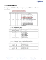
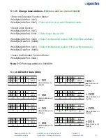
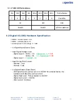
5.1.1.7 DIO I/O Port Address
DI4
DI3
DI2
DI1
DO4
DO3
DO2
DO1
Pin
Definition
7
6
5
4
3
2
1
0
Data
Bits
DI
DO
DIO
0xA03
0xA02
I/O
Port
address
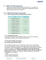
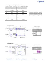
5.2 Digital I/O (DIO) Hardware Specification
•
XCOM+
:
Isolated
power
in
V+
•
XCOM
‐
:
Isolated
power
in
V
‐
•
Isolated
power
in
DC
voltage
: 5
~
48V
• 4 x Digital Input (Source Type)
• Input Signal Voltage Level
- Signal Logic 0 :
XCOM+
=
5V,
Signal Low
-
V-
<
0.4V
XCOM+
>
5V,
V+
-
Signal Low
>
4.6V
- Signal Logic 1 : >
XCOM+
-
3V
• Input Driving Sink Current :
- Minimal : 1 mA
- Normal : 5 mA
• 4 x Digital Output (Open Drain)
- DO Signal have to pull up
resistor
to XCOM+ for external device, the
resistance will affect the pull up current
- Signal High Level : Pull up resistor to XCOM+
- Signal Low Level : = XCOM-
- Sink Current: 1A (Max)
Summary of Contents for PowerTwin PS12-E3950C9
Page 12: ...Product Introductions Chapter 1...
Page 28: ...System Pin Definitions and Settings Chapter 2...
Page 38: ...System Setup Chapter 3...
Page 56: ...BIOS Setup Chapter 4...
Page 99: ...Product Introductions Chapter 1...
Page 129: ...System Pin Definitions and Settings Chapter 2...
Page 139: ...System Setup Chapter 3...
Page 157: ...BIOS Setup Chapter 4...

