Spectra
GmbH
&
Co.
KG
vertrieb@spectra.de
User
Manual
‐
Spectra
PowerTwin
P
Apollo
Lake
+
standard Displays
Version
1.0
September
2018
3
Chapter 3
System Setup
3.1 Removing the Top Cover .……...…………………………..…………... 52
3.2 Installing a Half Size Mini PCIe Card ……………………………….... 53
3.3 Installing a Full Size Mini PCIe Card ………………....…………….... 54
3.4 Installing Antennas …………………………………..….…………….... 55
3.5 Installing a SO-DIMM ……………………………………....…….….... 57
3.6 Installing CPU Thermal Pad ..……………………….….…………….... 58
3.7 Installing the Top Cover …………………………….….…………….... 58
3.8 Installing a SATA Hard Drive ………………………..….……………... 59
3.9 Installing a SIM Card ………………………………..….……………… 61
3.10 Connecting with Display Module ……..………..….……………....
62
3.11 VESA Mount ....………………………....…..….……………................ 64
3.12 Panel Mount..........................................…..….……………................ 65
Chapter 4
BIOS Setup
4.1 BIOS Introduction …….……….……….…….…….…..….…………... 70
4.2 Main Setup ……..……….…………….…….…..….………………...... 71
4.3 Advanced Setup ……………………….……….……………………….. 72
4.3.1 ACPI Settings ……..…………….……….………………………. 72
4.3.2 F81866 Super IO Configuration ..…….………………………... 73
4.3.3 Hardware Monitor ………………..…………………………….... 75
4.3.4 S5 RTC Wake Setting …….……..……………..……………..... 75
4.3.5 Serial Port Console Redirection ..……………..….……….….... 76
4.3.6 CPU Configuration ....……………………….……..…………..... 77
4.3.7 Network Stack Configuration ..……………….……………….... 78
4.3.8 CSM Configuration …………………………….………..………. 78
4.3.9 USB Configuration ………………………..…………………….. 80
4.4 Chipset Setup.…...……….………………….……….…..……………... 81
4.4.1 North Bridge ………….…………………….…………………….. 81
4.4.2 South Bridge ………….………………………………………….. 82
4.4.3 South Cluster Configuration …………………………………….. 83
4.5 Security Setup …...……….………………….……….…..……………... 86
4.6 Boot Setup …..……….….………………….……….…..….…………... 87
4.7 Save & Exit …...……….….………………….…..….…..…………….... 88
Chapter 5
Product Application
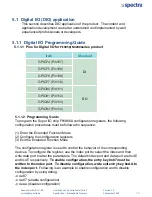
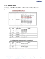
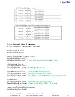
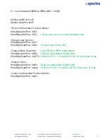
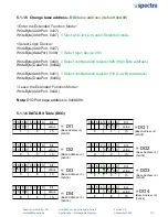
5.1 Digital I/O (DIO) application……………………….…..….…………….. 90
5.1.1 Digital I/O Programming Guide …….…………………………... 90
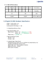
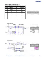
5.2 Digital I/O (DIO) Hardware Specification ……….….…………………. 95
Chapter 6
Optional Module Pin Definitions and Settings
6.1
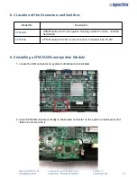
Location of the Connectors and Switches ……………..…………….. 98
6.2
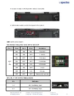
Installing a CFM-IGN Power Ignition Module …………..……………. 98
6.3
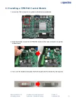
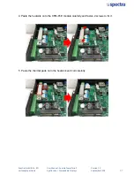
Installing a CFM-PoE Control Module ………………..………………. 100
Summary of Contents for PowerTwin PS12-E3950C9
Page 12: ...Product Introductions Chapter 1...
Page 28: ...System Pin Definitions and Settings Chapter 2...
Page 38: ...System Setup Chapter 3...
Page 56: ...BIOS Setup Chapter 4...
Page 99: ...Product Introductions Chapter 1...
Page 129: ...System Pin Definitions and Settings Chapter 2...
Page 139: ...System Setup Chapter 3...
Page 157: ...BIOS Setup Chapter 4...

