


EPSILON CLOCK MODEL EC1S
Spectracom Corporation
EPSILON CLOCK User’s Manual
2-2
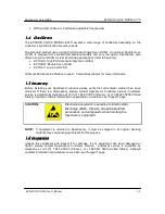
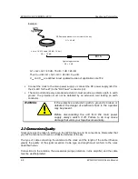
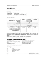
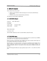
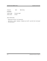
Example:
GPS
Signals
GPS ant enna placed in di rect view of the sky
50 m of KX13 cable (-30 dB / 100 m)
G1 = 40 dB
G2 = - 15 dB
EPSILON BOARD II
Light ening protect ion
G3 = -1 dB
G1 + G2 + G3 = 40 dB - 15 dB - 1 dB = 24 dB
Thus: X
min
dB < G1 + G2 + G3 = 24 dB < X
max
dB
X
min
and X
max
are defined in last updated revision of application note TF2.
•
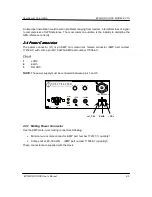
Connect the clock to the main power supply or connect the DC power supply (24V for
the 2S, 48V for the 2T) to the "DC Power" connector (J2).
•
The main outlet and every associated extension must provide a protective path to earth
ground. The protection must not be defeated by an extension cord lacking an earth
conductor.
WARNING:
If the protective conductor's path to ground is broken or
defeated, the danger of electrical shock to the operator
may be present.
Before disconnecting the unit from the main power
supply, always switch it off. Failure to do may cause
damage that voids your Spectracom warranty.
2.3
2.3
2.3
2.3
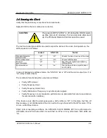
Connections Quality
Connections Quality
Connections Quality
Connections Quality
Great care must be taken in setting up the GPS Antenna and its connections. Remember that
your GPS antenna must have an unobstructed view of the sky.
The type of cable connecting the antenna to the clock and the length of the cable influence
greatly the quality of the signal reception. Cable type and length must conform to the rules
described herein.
Connections to the antenna, the accessories (surge protection, in-line amplifier) and the cable
must be weatherproofed.
EC1S