This Reference Phase Offset Data is plotted over time (abscissa) in the
Reference Mon-
itor
panel in the center of the screen. Use the check boxes in the
References
panel
(2)
to select the reference(s) for which you want to plot the phase offset data. Use the
handles
(3)
to zoom in on a time window.
The scale of the axis of ordinate
(4)
is determined by the largest amplitude of any of the
references displayed in the current time window. Use the checkboxes in the
Refer-
ences
panel on the right to remove references from the graph, or add them to it.
3.3.3
The GNSS Reference
With most applications, VelaSync will be setup such that it utilizes a GNSS signal as the
primary (if not the only) timing reference.
VelaSync's GNSS receiver utilizes the signal provided by the GNSS antenna.
The GNSS receiver analyzes the incoming GNSS data stream and supplies the GNSS
time and 1PPS (Pulse-Per-Second) signal to VelaSync's timing system. The timing sys-
tem uses the data to control the System Time and discipline the oscillator.
While VelaSync’s default GNSS receiver configuration will likely be adequate for most
applications, it is advisable that you review the options and change settings as needed,
particularly if you are experiencing poor signal reception.
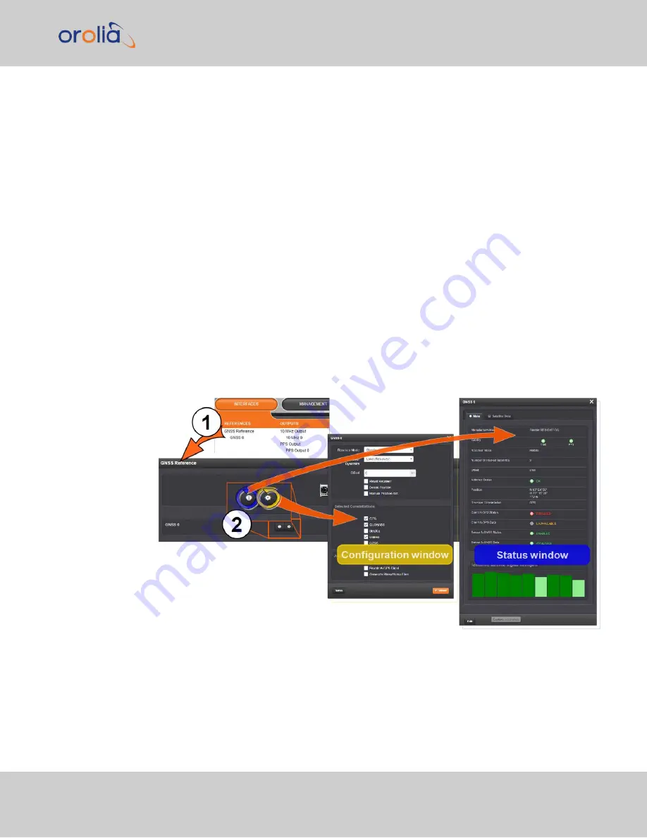
To access the GNSS Receiver settings:
3.3 Managing References
CHAPTER
3
•
VelaSync User's Manual Rev. 3
123
Summary of Contents for VelaSync 1225
Page 2: ......
Page 4: ...Blank page II VelaSync User s Manual...
Page 12: ...BLANK PAGE X VelaSync User s Manual TABLE OF CONTENTS...
Page 28: ...16 CHAPTER 1 VelaSync User s Manual Rev 3 1 7 The VelaSync Web UI...
Page 34: ...BLANK PAGE 1 9 Regulatory Compliance 22 CHAPTER 1 VelaSync User s Manual Rev 3...
Page 104: ...BLANK PAGE 2 11 Configuring PTP 92 CHAPTER 2 VelaSync User s Manual Rev 3...
Page 251: ...Server management System specifications VelaSync User s Manual 239 APPENDIX...
Page 267: ...VelaSync User s Manual 255 APPENDIX...


