14215700-IG, Edition 15.0
May 2020, Original document
100
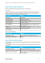
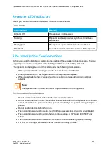
Repeater LED Indicators
Below you will find information about LED indicators on the repeater.
Front Cover
LED Indicator
Meaning
Indicator Off
The repeater is not powered.
Flashing
Repeater has been powered, sync has still not been
established.
Steady green
The repeater is powered and sync is established.
Short flash
A handset connects or makes handover to the repeater.
Site Installation Considerations
Before you begin the installation, determine the position of the repeater for best coverage. The cov-
erage depends on the construction of the building and the choice of building materials.
The repeater can be registered on the system under the following circumstances.
l
When placed within the coverage area of a base station/server 200/400.
l
When placed within the coverage area of an already-installed repeater.
l
When placed outside the coverage area of a base station or repeater using an external
antenna.
Note:
The repeater does not add channels. It only adds additional coverage area.
Environmental Considerations
l
Do not install a device near metal objects and steel constructions.
l
Do not position devices in ducts, plenums or hollow spaces used to transport environmentalair
except where the duct, plenum or hollow space is created by a suspended ceiling having lay-in
panels.
l
Do not position devices behind furniture.
l
The installation area must be clean, free of traffic and excess dust, dry, and well ventilated.
l
The installation area must be within the temperature ranges of 10°C and 40°C/50°F and
104°F.
l
The installation area must be between 20% and 80% non-condensing relative humidity.
l
For best RF coverage, the device must be mounted vertically on walls.
Spectralink IP-DECT Server 200/400/6500 and Virtual IP-DECT Server One Installation and Configuration Guide


