background image

SpectraLink Corporation 

Installation, Configuration, and Administration  


NetLink Telephony Gateway  

Part Number: 72-0065-02-R.doc 

Page 50 

Example: If the Transfer feature key sequence is “Flash Star 7” and you wish to 
keep the default at 

FCN

+

2

, navigate to key 2, press Enter, type F*7 and press 

Enter. 

4.


Repeat for each feature you wish to program to a function key macro. 

Remember to note the features and macros so that they can be edited in the handset 
menu, if necessary, and programmed into any other NetLink Telephony Gateways 
on the same PBX if Send All is not being used. 
When you have finished programming the macros, press Esc to return to the 

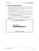
NetLink Wireless Telephone System 

menu. 

16.3


Programming the ADMIN Feature 

The 

ADMIN

 option allows the system administrator to add and delete handsets via 

another handset, rather than via the NetLink Telephony Gateway. Any function key 

sequence may be programmed to 

ADMIN

 by typing ADMIN next to the desired key. 

The ADMIN feature may be programmed on only one NetLink Telephony Gateway 
(the one that contains the line used by the system administrator) in order to limit its 
accessibility system-wide. 
When the ADMIN function is active, pressing the function key sequence on the 
handset will open the ADMIN function. The following steps allow the administrator 
to add or delete a handset: 
1.


Press 

FCN

 plus the assigned key. Once in the ADMIN function, pressing the 

FCN


key will cancel the action and return to the previous menu level. 

2.


Enter the NetLink Telephony Gateway password using the handset keypad. 
Note that the password is case sensitive. The key steps through each letter and 
number as it is repetitively pressed. 

3.


Once the password is accepted, the NetLink Telephony Gateways are listed. Use 

the arrow keys to scroll through the list. Press 

0

 (the zero key) to select the 

correct NetLink Telephony Gateway. 

4.


The handsets assigned to the selected NetLink Telephony Gateway are listed by 
the last three byte numbers in the MAC address. If a line is not assigned to a 
handset, not used will display. Use the arrow keys to scroll through the lines. 

5.


Display the line to add or delete a handset and follow the prompts displayed on 
the handset. 

6.


If a name or extension must be associated with an added handset for record 
keeping purposes, it must be entered on the NetLink Telephony Gateway 

Telephone Line Configuration

 screen. 

Summary of Contents for TGA108

Page 1: ...NetLink Telephony Gateway Installation Configuration and Administration Utilizing SpectraLink Radio Protocol SRP Part Number 72 0065 02 Issue R ...

Page 2: ... to lost profits arising out of or related to this document or the information contained in it even if SpectraLink has been advised knew or should have known of the possibility of such damages Trademark Information SpectraLink LinkPlus Link NetLink SVP Are trademarks and registered trademarks of SpectraLink Corporation The SpectraLink logo is a registered trademark in the United States of America ...

Page 3: ...utions while installing telephone equipment Never install telephone wiring during a lightning storm Never install telephone jacks in wet locations unless the jack is specifically designed for wet locations Never touch uninsulated telephone wires or terminals unless the telephone line has been disconnected at the network interface Use caution when installing or modifying telephone lines ...

Page 4: ...5 1 Prepare Demarcation Demarc Blocks 17 5 2 Install Telephone Demarc Blocks 17 5 3 Assign and Program Telephone Ports 17 5 4 Connect Telephone Lines to Demarc Blocks 18 6 Pre Installation Verification 22 6 1 Verify Pre Installation Requirements 22 6 2 Check Components 22 7 Install NetLink Telephony Gateway 24 7 1 Mount to Rack or Wall 24 7 2 Installing Multiple NetLink Telephony Gateways 25 7 3 C...

Page 5: ...2 Programming Analog PBX Features 49 16 3 Programming the ADMIN Feature 50 17 Menu Programming no softkeys 51 18 Softkey and Shortcut Key Programming 53 19 NetLink Docking Station Feature Keys Programming 57 20 Software Maintenance 60 20 1 Software Updates 60 20 2 Updating Larger Systems 61 20 3 Using FTP 61 20 4 Upgrading Wireless Telephones 62 20 5 Backup and Restore NetLink Telephony Gateway Co...

Page 6: ...es a number corresponding to the type of PBX Available at http www spectralink com consumer interface_guides jsp NetLink Wireless Telephone WLAN Compatibility List 72 9000 00 Access Point Configuration Note 72 99xx 00 where xx indicates a number corresponding to the type of access point Available at http www spectralink com resources wifi_compatibility jsp Deploying Enterprise Grade Wi Fi Telephon...

Page 7: ...ces NetLink Wireless Telephones operate as clients on the wireless LAN alongside other mobile 802 11 devices Wireless LAN fixed radios called access points APs receive IP voice packets from handsets and forward them to the NetLink Telephony Gateway over the Ethernet LAN The Telephony Gateway connects to the host telephone switch using digital or analog line interfaces Using SpectraLink s exclusive...

Page 8: ...stalled in a system with four or fewer Gateways the IPC cables are not required If there are five or more Gateways in the system then one or more NetLink SVP Server must be installed to handle the increased load and additional timing requirements See NetLink SVP Server Installation Configuration and Administration 2 4 System Speed NetLink Wireless Telephones can operate up to 54 Mb s in 802 11a an...

Page 9: ...er example NetLink SVP Server Ethernet Switch access point Wireless POS Wireless Telephones access point desksets optional PBX NetLink Telephony Gateway NetLink Telephony Gateway NetLink Telephony Gateway NetLink Telephony Gateway NetLink Telephony Gateway Device supplied by SpectraLink Administrative computer Demarc Block TFTP Server CAT 5 cable 25 pair cable Multiple phone cables Phone cable ...

Page 10: ...y that works with telephone systems CO PBX or Key Systems with analog loop start ports Access points Access points APs are supplied by third party vendors APs provide the connection between the wired Ethernet LAN and the wireless 802 11 LAN APs must be positioned in all areas where NetLink Wireless Telephones will be used The number and placement of APs will affect the coverage area and capacity o...

Page 11: ...Link SVP Server supports 120 simultaneous handset calls Multiple SVP Servers can be installed to maximize system capacity TFTP server Required in the system to distribute software to the handsets Administrative computer An administrative computer is required for setup and maintenance of the NetLink Telephony Gateway and the NetLink SVP Server This computer may be only temporarily connected to the ...

Page 12: ...ere is a network connection ACT Lit if there is system activity COL Lit if there are network collisions 5 Network Connects to wired Ethernet LAN using a 10Base T RJ 45 connector 6 Error LED Lit when the system has detected an error 7 Status LEDs Indicate system error messages and status 1 Heartbeat that indicates gateway is running 2 Lit if line s in use 3 Currently unused 4 Timing Master 5 Lit if...

Page 13: ...a qualified SpectraLink installer assists the customer in completing the remaining steps 1 Site Preparation Done by the customer or a wire technician contractor 2 NetLink Telephony Gateway Installation Done by the customer or SpectraLink If five or more NetLink Telephony Gateways are to be installed a NetLink SVP Server is required and would also be installed in this step 3 NetLink Telephony Gatew...

Page 14: ...e powered on and off at the same time Cross Connect Block Required to connect the PBX ports to the NetLink Telephony Gateway s 25 Pair Cables RJ 21 male at NetLink Telephony Gateway end required to connect each NetLink Telephony Gateway to the cross connect blocks Backboard space The NetLink Telephony Gateway and the NetLink SVP Server are designed to be wall mounted to plywood securely screwed to...

Page 15: ...gure a wireless LAN to support NetLink Telephony Gateways and wireless telephones refer to Deploying NetLink Wireless Telephones Best Practices IP Addressing The NetLink Telephony Gateway along with each of the handsets associated with it requires an IP address The system administrator must determine what IP addresses are to be used by the NetLink Telephony Gateway and APs Handsets can be configur...

Page 16: ...igned to be wall mounted vertically or horizontally over plywood or mounted in a standard 19 inch rack mount cabinet with a Rack Mount Kit Locate the NetLink Telephony Gateway and NetLink SVP Server in a space with Sufficient backboard mounting space and proximity to the LAN access device switched Ethernet switch telephone switch and power source Easy access to the front panel which is used for ca...

Page 17: ... or key system The interfaces are intended to connect to digital PBX ports that provide signals of 5Vp p max AC components Some PBXs provide a 48 V DC offset Modem administration The NetLink Telephony Gateway can also be accessed remotely using its internal modem and a dedicated telephone line If your site will use administration by modem this connection should be included in the wiring installati...

Page 18: ...nes to Demarc Blocks Telephone cables are punched down onto the cross connect blocks as shown in the following demarc block diagrams Photocopy the Wireless Device Planning Worksheets as needed Use the forms to track the telephone line assignments connected to each NetLink Telephony Gateway As the installer punches down each telephone connection record the information on the form to identify the us...

Page 19: ...r digital interface should be wired as follows LINE1 tip ring LINE 2 tip ring LINE 3 tip ring LINE 4 tip ring LINE 5 tip ring LINE 6 tip ring LINE 7 tip ring LINE 8 tip ring LINE 9 tip ring tip ring tip ring tip ring LINE 13 tip ring LINE 14 tip ring LINE 15 tip ring LINE 16 tip ring 25 PAIR MALE CONNECTOR CABLE TO GATEWAY CONNECTOR A Telephone Ports LINE 10 LINE 11 LINE 12 UNUSED PAIRS DO NOT USE...

Page 20: ...ould be wired as follows Line 1 TX tip ring Line 2 TX tip ring Line 3 TX tip ring Line 4 TX tip ring Line 5 TX tip ring Line 6 TX tip ring Line7 TX tip ring Line 8 TX tip ring Line 9 TX tip ring tip ring tip ring tip ring Line 13 TX tip ring Line 14 TX tip ring Line 15 TX tip ring Line 16 TX tip ring 25 PAIR MALE CONNECTOR CABLE TO GATEWAY CONNECTOR A Telephone Ports Line 10 TX Line 11 TX Line 12 ...

Page 21: ...g Line 4 RX tip ring Line 5 RX tip ring Line 6 RX tip ring Line 7 RX tip ring Line 8 RX tip ring Line 9 RX tip ring Line 10 RX tip ring Line 11 RX tip ring Line 12 RX tip ring Line 13 RX tip ring Line 14 RX tip ring Line 15 RX tip ring Line 16 RX tip ring 25 PAIR MALE CONNECTOR CABLE TO GATEWAY CONNECTOR B Telephone Ports Unused Pairs Note RX denotes data received by the telephone system from Gate...

Page 22: ...mponents The following items should be at the installation site NetLink Telephony Gateway Depending on the size of your system there may be four or more NetLink Telephony Gateways which will be linked together to support additional users AC Adapter Supplies power to the NetLink Telephony Gateway Use only the provided Class II AC Adapter with output 24VDC 1A Screws Four inch 8 panhead screws for ea...

Page 23: ...y Part Number 72 0065 02 R doc Page 23 NetLink SVP Server If required see next section Modem Cable DB 9 female null modem cable Required for initial setup of the NetLink Telephony Gateway and SVP Server Documentation Provided on compact disk CD SpectraLink Installation Manuals User Documentation ...

Page 24: ...physically touching Mount the NetLink Telephony Gateway to rack The Rack Mount Kit is designed for mounting equipment in a standard 19 inch rack and should contain the following equipment Mounting plates Two for each Gateway to be mounted Screws Four rack mount screws for each Gateway to be mounted Follow these steps to mount the Gateway to a rack 1 Remove the corner screws from the Gateway 2 Scre...

Page 25: ...vertical mount or left horizontal mount of adjacent units 2 Place the ESD strap over the pilot holes that span two units and hold it against the plywood backboard or rack 3 Place the star washer on top of the ESD strap 4 Insert the 8 x screw and tighten to leave 1 8 to 1 4 inch gap from the wall 5 Repeat for all ESD straps When installing a TGA116 the grounding terminal in the rear panel of each u...

Page 26: ... E R R O R 1 2 3 4 5 STATUS RS 232 L N K O K A C T C O L IPC NETWORK OUT IN IPC NETWORK OUT IN IPC NETWORK OUT IN IPC NETWORK OUT IN Maximum spacing between units 1 2 inch Four Unit NetLink Telephony Gateway Rack mount or horizontal wall mount formation unit one is at the bottom No IPC cable is connected to the IN port of the first unit or to the OUT port of the last unit When installing a system ...

Page 27: ... switch Using an RJ 45 cable connect the NETWORK port on each NetLink Telephony Gateway to the connecting port on the same Ethernet switch Connect power 1 Connect the power plug from the AC adapter to the jack labeled PWR on the NetLink Telephony Gateway Use only the provided Class II AC Adapter with output 24VDC 1A For proper operation all NetLink Telephony Gateways must be powered on and off at ...

Page 28: ...istration document that is used in conjunction with this one for complete system configuration and administration See NetLink e340 h340 i640 Wireless Telephone Configuration and Administration or NetLink 8000 Series Wireless Telephone Configuration and Administration APs move information between the wireless local area network LAN and the wired LAN They are NOT configured from the Administration C...

Page 29: ... LinkPlus Interface Guide for your telephone system 9 At this point the NetLink Telephony Gateway is configured The remaining steps are done on the handsets These steps are detailed in the handset administration document NetLink e340 h340 i640 Wireless Telephone Configuration and Administration or NetLink 8000 Series Wireless Telephone Configuration and Administration 10 Configure test and verify ...

Page 30: ...hted field Enter the Enter key will either display the options associated with an item or allow you to type an entry into the field Exit Screen Esc the Esc key will take you to the previous screen Move one line up Move one line down Move one field to the left Move one field to the right Corresponding arrow key Scroll If a screen has more lines of information than can be displayed at once the scrol...

Page 31: ...address 9 1 Connect via the Serial Port The serial connection is used in lieu of DHCP in systems that choose not to assign NetLink Telephony Gateway IP addresses via a DHCP Server in which case a static IP address is required 1 Using a DB 9 female null modem cable connect any NetLink Telephony Gateway to the serial port of a terminal or PC 2 Run a terminal emulation program such as HyperTerminal o...

Page 32: ...ay Configuration screen and reset the Gateway Once you have established the IP address via the Network Configuration menu and reset the Gateway you may use Telnet to continue the configuration of the Gateway 4 If you have multiple NetLink Telephony Gateways to configure with static IP addresses ensure each one is connected to the Ethernet Switch as shown in the Installation sections of this docume...

Page 33: ...splays the hostname and IP address of the NetLink Telephony Gateway on which you are currently operating 9 4 Connecting Via External Modem The external modem method of connection is most frequently used for routine maintenance of the system when administration of the system is remotely done and the network itself is not remotely accessible You will need a standard analog phone line for the modem A...

Page 34: ...r The settings should match those shown in the following figure which was taken from ProComm Plus Connect the Modem Unplug the modem from the PC s serial port and plug it into the NetLink Telephony Gateway 9 5 Connecting via Internal Modem An internal 2400 baud modem is built into the NetLink Telephony Gateway Line one can be configured to connect via this modem The modem is only used by SpectraLi...

Page 35: ...ations links Used to view the system operation and troubleshoot problem areas Telephone Line Configuration Used to add delete and maintain handsets Gateway Configuration Used to enter and maintain configuration information for the operation of the NetLink Telephony Gateway Network Configuration Used to enter and maintain configuration information for the NetLink Telephony Gateway as a component on...

Page 36: ...minimal settings required for NetLink Telephony Gateway functioning Additional settings may be required by your system Do not change settings until you have studied this section and are familiar with the consequences any change will produce When the settings marked with an arrow bullet are changed the NetLink Telephony Gateway automatically goes into Maintenance Lock and prevents any new calls fro...

Page 37: ...tion DNS server and DNS domain These settings are used to configure Domain Name services Consult your system administrator for the correct settings These can also be set to DHCP This will cause the DHCP client in the gateway to attempt to automatically get the correct setting from the DHCP server The DHCP setting is only valid when the IP address is also acquired using DHCP WINS servers These sett...

Page 38: ...NETLINK COMMON TXT NETLINK CAPABILITIES TXT IGMP Internet Group Management Protocol Yes enables No disables This is used for managing multicast traffic It should typically be set to Yes Maintenance Lock The system automatically sets this option to Yes after certain maintenance activities that require reset These are indicated in this list with an arrow bullet Maintenance Lock prevents any new call...

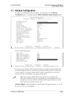
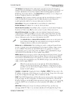
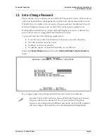
Page 39: ... is desired the passwords must be set in each NetLink Telephony Gateway A password must meet the following requirements It must be more than four characters but cannot exceed 16 characters The first character must be a letter Numbers or letters are allowed No dashes spaces or punctuation marks etc are allowed Select the Change Password option from the NetLink Wireless Telephone System menu If you ...

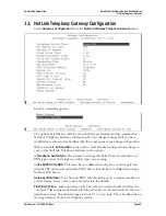
Page 40: ...ttings to every other NetLink Telephony Gateway in the system Telephone Switch Type Press Enter to change this field From the sub menu of PBX types select the telephone switch type you are using Use SVP100 for QOS This must be set to No when using four or fewer gateways with the IPC cables and no NetLink SVP Server It must be set to Yes when using a NetLink SVP Server Gateway ID Number For a Norst...

Page 41: ...ess If the OAI Gateway is on another subnet NONE If no OAI Gateway is on the system TFTP Download Master This entry indicates the source of software updates for the handsets associated with this NetLink Telephony Gateway Software updates received from SpectraLink must be placed in this location See section 20 Software Maintenance for more information When the handset is turned on it checks this so...

Page 42: ...m automatically sets this option to Yes after certain maintenance activities that require reset and certain alarms that cause the system to be inoperable Such maintenance activities are indicated in this list with an arrow bullet Maintenance Lock prevents any new calls from starting Note that the administrator cannot change this option It is automatically set by the system Reset the system at exit...

Page 43: ...and Administration NetLink Telephony Gateway Part Number 72 0065 02 R doc Page 43 Reset All Systems If this option is selected you will be prompted to reset all NetLink Telephony Gateways Press Esc to return to the NetLink Wireless Telephone System menu ...

Page 44: ...maintenance procedure that requires any one NetLink Telephony Gateway to be reset either via Maintenance Lock or manually via Reset System Resetting them all keeps the NetLink Telephony Gateways synchronized which is important for proper system functioning The NetLink Telephony Gateways are ready to operate The next step is to configure the lines used by the handsets See the next section Telephone...

Page 45: ...creen 14 1 Adding or Changing a Handset When adding or changing a handset a MAC address must be entered Handset registration may be accomplished over the air by simply selecting the appropriate line MAC address field with the arrow keys typing R for On Air Register and powering on the handset The MAC address is automatically captured Optionally the party s name and extension number may be recorded...

Page 46: ...orksheet 4 Repeat steps 2 3 and 4 for each handset to be added or changed 5 Press Esc to return to the NetLink Wireless Telephone System menu A handset may be associated with one and only one telephone line The same MAC address may not be assigned to two or more telephone lines 14 2 Deleting a Handset To delete a handset from the NetLink Telephony Gateway configuration 1 Navigate to the NetLink Wi...

Page 47: ...ogrammed button on a deskset The Feature Programming option is used in systems that either do not have NetLink Wireless Telephones that use softkeys or in systems that have a combination of NetLink Wireless Telephones some models with softkeys and some without In systems that only use NetLink Wireless Telephones with softkeys the NetLink e340 h340 i640 and 8000 Series Wireless Telephones all featu...

Page 48: ...program special features With Feature Programming you can access special features by pressing the FCN key on the handset followed by another key This shortcut is called a macro You may define macros for the digits 1 9 0 and After programming when you press FCN followed by a digit or character you will have access to the associated feature The feature programming settings are usually the same for e...

Page 49: ...w 1 The table below displays the default menu options that are programmed into the handsets for an analog system You may set these same functions here or change them to something else If you change them be sure to enter the corresponding changes in the Menu Programming screen in the next section Function Key Feature Key Sequence FCN 1 Mute MUTE FCN 2 Xfer FCN 3 Conn FCN 4 Conf FCN 5 Fwd FCN 6 Redi...

Page 50: ...ministrator in order to limit its accessibility system wide When the ADMIN function is active pressing the function key sequence on the handset will open the ADMIN function The following steps allow the administrator to add or delete a handset 1 Press FCN plus the assigned key Once in the ADMIN function pressing the FCN key will cancel the action and return to the previous menu level 2 Enter the N...

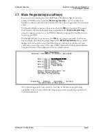
Page 51: ...re programming established in the Feature Programming screen for analog systems or in the PBX for digital systems per the LinkPlus Interface Guide for your PBX The handset displays four menus as the FCN key is pressed repeatedly Each menu has two display lines that are programmed in the Menu Programming screen which displays all four menus at once The default factory settings are for features most...

Page 52: ... system Each of the four menus displays two lines The numbers followed by the equal sign indicate which key to press on the handset to activate the feature such as 2 Xfer Transfer These lines will display on the handset exactly as programmed here All NetLink Telephony Gateways should be programmed identically If any of the factory defaults have been changed via Feature Programming or in the steps ...

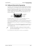
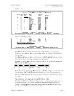
Page 53: ...eir corresponding display areas on the handset are shown below The handset emulates a specific deskset in your vendor s PBX system See the LinkPlus Interface Guide for your system for emulation information The shortcut keys are 1 9 0 and Any shortcut key may be pressed by the user while scrolling through the softkeys or while in the shortcut menu to activate a feature The feature will activate whe...

Page 54: ...ure Level 0 softkey C displayed as Xfer and with the 8 shortcut Level Softkey Shortcut Menu Label Softkey Label Action 0 C 8 Transfer Xfer F8 With the above programming Xfer will appear in the Cccc display area at Level 0 and the end user can use the FCN 8 shortcut or press the C softkey to transfer a call Use the LinkPlus Interface Guide for your system to determine what features to assign to sof...

Page 55: ...el Mail Action F2 Activates message retrieval L Used with 0 9 Sends a message to the PBX to activate the feature associated with this sequence Label ReleaseLine Action L0 Releases the current line appearance MUTE Mutes handset Label Mute Action MUTE Activates Mute function in handset ADMIN Initiates Admin sequence Label Admin Action ADMIN Activates an administrative function in the PBX OAI Used wi...

Page 56: ...ration and Administration NetLink Telephony Gateway Part Number 72 0065 02 R doc Page 56 Use this table to develop your own programming correspondence Level Softkey Shortcut Menu Label Softkey Label Action 0 A B C D 1 A B C D 2 A B C D 3 A B C D ...

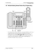
Page 57: ...ble Feature Keys along the right side These may be programmed for line appearances or features Additionally there are three programmable keys along the bottom of the NetLink Docking Station that are labeled CONF TRNSFR HOLD These keys should be programmed to match their labels The LINE key cannot be programmed it is hard coded to activate line appearances The four softkeys under the display are pr...

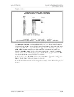
Page 58: ... line appearances Line 1 through Line 9 CONF XFER and HOLD refer to the three programmable feature keys under the keypad The Label column allows a convenient description if needed The Action column allows you to enter the key sequence that has been programmed in the PBX to activate the feature you wish to assign to this key In the example above Keys 1 6 remain at their default line appearance sett...

Page 59: ... in Docking Station when Line 6 is pressed ADMIN Initiates Admin sequence Key 5 Label Admin Action ADMIN Activates an administrative function in the PBX when Line 5 is pressed OAI Used with 0 9 Initiates assigned application Key 7 Label Phone Book Action OAI7 Activates application that opens an OAI application e g company phone book when Line 7 is pressed FLASH Initiates hookflash Key 4 label Flas...

Page 60: ...Link component Device update method File name NetLink 150 Telephony Gateway FTP file name to NetLink Telephony Gateway fnctla bin auxlry bin OAI Telephony Gateway mog600 bin Automatic from NetLink Telephony Gateway as set in the TFTP Code Update screen for OAI See NetLink Wireless Telephone OAI Gateway Installation NetLink Wireless Telephones Automatic from network TFTP Server as set in the Gatewa...

Page 61: ...n how this is done but generally allow you to delete files in the host and client location To transfer the software using FTP 1 Connect to the Telephony Gateway using the command FTP hostname or FTP IP address 2 Log in using the administrator login admin and password default is admin A login confirmation message will display followed by the FTP prompt 3 At the FTP prompt type binary A confirmation...

Page 62: ... perform their checkout after the call has been completed Normal Download Messages When the handset is powered on it displays a series of messages indicating that it is searching for new software checking the versions and downloading The normal message progression is Message Description Checking Code Handset is contacting the Download Master to determine if it has a newer version of software that ...

Page 63: ... was being downloaded yy is an error code describing the particular failure Possible error codes are 01 TFTP server did not find the requested file 02 Access violation reported from TFTP server 07 TFTP server reported No such user error Check the TFTP server configuration 81 File put into memory did not CRC The handset will attempt to download the file again FF Timeout error TFTP server did not re...

Page 64: ...use the get command to transfer the required files from the NetLink Telephony Gateway to the server get config bin Restore At the FTP prompt use the put command to transfer the required files from the server to the NetLink Telephony Gateway put config bin The get and put commands will copy files If you have multiple NetLink Telephony Gateways be careful not to overwrite the config bin files To avo...

Page 65: ...gh understanding of the configuration of the system and the information contained in this document is necessary for anyone who wishes to handle system malfunction Information about telephone line status system alarms and network status displays on various screens accessed through the System Status Menu screen opened from the NetLink Wireless Telephone System menu of each Telephony Gateway Access P...

Page 66: ...y Gateway Part Number 72 0065 02 R doc Page 66 Options on the System Status Menu provide a window into the real time operation of the components of the NetLink Wireless Telephone System Use this data to determine system function and to troubleshoot areas that may be experiencing trouble ...

Page 67: ... in communication with this AP MaxWTs The maximum number of handsets that have simultaneously used the AP since last reset NotBest The number of times a handset indicates that it is not using the best AP Last Heard The time a report from a handset was received that included information about the AP A significant difference between Last Heard and System Uptime indicates that the AP has not been use...

Page 68: ...tallation Configuration and Administration NetLink Telephony Gateway Part Number 72 0065 02 R doc Page 68 Unless noted otherwise times are displayed using the format D HH MM SS D is day HH is hours MM is minutes and SS is seconds ...

Page 69: ...system malfunction Some of these alarms are easily remedied and others require a call to SpectraLink s Customer Support Department From the System Status Menu select Error Status The screen displays active alarms on the NetLink Telephony Gateway The following sample screen displays two Line Sync alarms The tables on the following pages display the list of alarm types display messages and descripti...

Page 70: ...rvice Config No Flash1 data Bad software or bad flash memory Config Too many wireless gateways More than five NetLink Telephony Gateways on the network without correct NetLink SVP Server setup Check the NetLink SVP Server for QOS setting in NetLink Telephony Gateway setup menu or remove NetLink Telephony Gateways from the network Config Unexpected SVPII box found on net A NetLink SVP Server is on ...

Page 71: ...le Bad software load on NetLink Telephony Gateway DAA DSP 1 keepalive Hardware problem on NetLink Telephony Gateway Reset If problem persists call SpectraLink Customer Service DAA DSP 2 keepalive Hardware problem on NetLink Telephony Gateway DAA DSP 1 download Hardware problem on NetLink Telephony Gateway DAA DSP 2 download Hardware problem on NetLink Telephony Gateway DAA AUX DAA Unknown Hardware...

Page 72: ...ware problem on NetLink Telephony Gateway Alarm Message Error Description Action Note Module alarms listed below should only occur in conjunction with CT DAA alarms shown above Correct the CT DAA alarms first and if the Module alarm persists contact SpectraLink Customer Support Module Init data failed Internal software error usually seen in conjunction with other errors Module Verify NetLink Telep...

Page 73: ...tomer Service Provide software version information If versions are compatible contact network administrator Radio SRP Invalid Hook State Incompatible software between handset and NetLink Telephony Gateway Call SpectraLink Customer Service Provide software version information Radio Key Buffer Full Key presses are too fast to process Slower key presses Radio SRP Opcode Error Incompatible software be...

Page 74: ...C Clear while viewing this display User Time Period The length of time in seconds statistics will accumulate in the Userpkts column before resetting to zero When troubleshooting a problem use this setting to isolate statistics for a given time period for example one hour This is the only field in this screen that can be changed by the user The rest of the display is a table of Ethernet statistics ...

Page 75: ...has signaled the microprocessor that it has received or sent a packet Collisions The number of times the Ethernet controller has attempted to send a packet but another device on the network transmitted at the same time corrupting the transmission Collision Drops The number of packets the Ethernet controller has discarded because there were over sixteen collisions After sixteen collisions the Ether...

Page 76: ... will involve From the System Status Menu select Telephone Line Status The NetLink Telephony Gateway supports up to 16 lines A sample NetLink Telephony Gateway screen is displayed below Line Telephone line number 1 16 Name Person or name associated with the line for identification purposes Extension Extension number associated with the line for identification purposes Status Status of the lines fr...

Page 77: ...2 R doc Page 77 ChkIn The handset has checked in and is in communication with an AP In Call The handset is in use Calls Duration The total number of calls made on this line since the system was brought up and the total duration of the calls System Uptime Length of time the NetLink Telephony Gateway has been powered on ...

Page 78: ...ing statistics by calculating the number to increase quickly when retries begin As retries lessen to zero and the transmissions become more reliable the number peaks and decreases slowly Viewing speed of increase decrease as well as total count reached will give you an accurate picture of the Retry and Missed characteristics TX Retry The rate at which packets the handset sent to the AP had to be r...

Page 79: ... Administration NetLink Telephony Gateway Part Number 72 0065 02 R doc Page 79 Num Calls The number of currently active calls on the NetLink Telephony Gateway Max Simul Calls The maximum number of simultaneous active calls on the NetLink Telephony Gateway ...

Page 80: ...y running on the components This information will help you determine if you are running the most recent version and will assist SpectraLink Customer Support in troubleshooting software problems From the System Status Menu select Software Version A sample NetLink Telephony Gateway screen is displayed below If obsolete versions are listed here use your FTP program to delete them to make room for new...

Page 81: ...y Gateway NetLink Telephony Gateway Hostname ____________________________________________________ MAC _________________________________ IP Address _____________________________ Subnet Mask __________________________ Host Switch Type _______________________ Wireless Telephones per AP _______ Telnet Port ID __________________________ Gateway Port Dialing Extension MAC Address Switch Port ID IP Addre...

Page 82: ... Normal 63 Downloading Software Updates 61 Erasing memory 63 Error Status 70 Ethernet switch description 12 External Modem 35 Feature Programming configuration of 49 FTP Procedure 62 Hotline 8 Interface Modules types 19 IPC Cables 24 MAC Address 47 Macros 49 Menus configuration of 52 Mute function 49 NetLink Telephony Gateway Alarms 70 Components 24 Description 12 Front Panel 14 Location 18 Mounti...

Reviews: