SpectraPure
®
SpectraPure
®
Inc.
480.894.5437 Call us toll-free 1.800.685.2783
2167 East Fifth St, Tempe, Arizona 85281
8
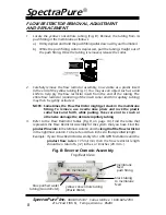
Fig. B: Reverse Osmosis Assembly
Top/Rear View
membrane
feed
push fitting
black tubing
to membrane
feed
RO membrane
yellow concentrate tubing
(Waste Water)
blue purified water
tubing (Good Water)
FLOW RESTRICTOR REMOVAL, ADJUSTMENT
AND REPLACEMENT
1. Locate the yellow concentrate tubing (Fig. B). Remove the tubing from its
push fitting at the membrane as follows:
a.) Firmly depress and hold the push fitting collar down with your thumbnail.
b.) While the push fitting collar is depressed, pull the tubing straight out of
the push fitting. Once the tubing is removed, release the collar.
2. Carefully remove the flow restrictor assembly, now visible as a plastic insert
In the end of the yellow tubing (Fig. C). You may use an object such as a dull
knife to help pry the flow restrictor insert from the end of the tubing. The
entire flow restrictor (consisting of the insert collar and thin capillary tubing)
may then be gently extracted.
NOTE: Sometimes, the Flow Restrictor might get stuck in the membrane
fitting. To remove, use needle nose pliers and rock the plastic
collar back and forth, while pulling. Take care not to crush or
otherwise damage the delicate capillary tubing
.
3. Refer to the Flow Restrictor Tables (Fig. D on page 10). Find the table that
represents the Flow Restrictor Assembly for the system that you have. Find the
product flow rate
in the leftmost column and the
length of the flow restrictor
in the rightmost column. To be safe, add two inches to that specified length.
Example: If your Flow Restrictor Assembly is for a 90 GPD Membrane and the
product flow rate
is 175 ml/min, then the flow restrictor length
should be a total of 6 (+2) inches, or 8 inches (20.3 cm.).


