CHAPTER 2 | SPECIFICATIONS
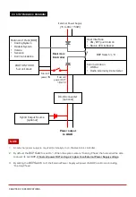
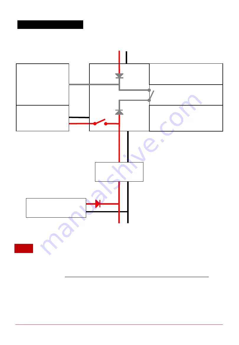
2.3 SYSTEM BLOCK DIAGRAM
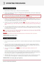
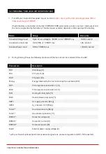
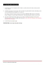
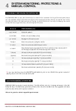
1. An external power supply is required to initially turn on the electronic controller.
2. By default, the
BOP Switch
is set to 1. When the system enters “Running Phase” the fuel cell will be able
to power its own BOP,
if Fuel cell power OUT voltage is higher than External Power Supply voltage.
3. By setting the
BOP Switch
to 0, the External Power Supply will power the BOP at all times including
“Running Phase”.
Fuel cell
power IN
Power output
to LOAD
User Interface
•
ON/OFF push button
•
Status LED & Buzzer
Communication
•
USB or
•
Radio telemetry transmitter
External Power Supply
(15 to 90V, 150W)
Fuel cell
power OUT
18-27V
Hybrid Output Source
(optional)
DC-DC converter
(optional)
NOTE
PROTIUM-1000
fuel cell stack
Balance of Plant (BOP)
•
Cooling System
•
Oxidant System
•
Valves
•
Sensors
•
Communications
BOP Switch 1/0
Electronic
Controller


