background image

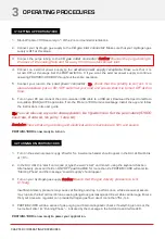
1. Turn ON your load and draw power as per normal. 

Caution: never pull the fuel cell voltage below 18V or 

draw power beyond 1000W.

If hybrid battery is connected at the load, PROTIUM-1000 will provide up to its maximum rated output and 
the rest is augmented by the battery. The total power available depends on the capacity of the battery.  

3.3 POWERING YOUR LOAD WITH PROTIUM-1000

CHAPTER 3 | OPERATING PROCEDURES

Mode

Range

Ramp-rate

Constant Voltage Load

Open circuit voltage to 18VDC min or 1000W max

-1VDC/second

Constant Current Load

0A to 55A or 1000W max

+2A/second

Constant Power Load

0W to 1000W max

+100W/second

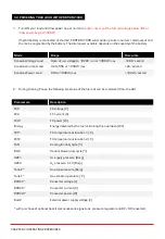
2. During Running Phase, the following live status of the fuel cell can be monitored from the GUI.

Parameters

Description

FCV

FC voltage (V)

FCA

FC current (A)

FCW

FC power (W)

Energy

Energy delivered by the fuel cell during this operation (Wh)

FCT1

FC temperature at location 1 (˚C)

FCT2

FC temperature at location 2 (˚C)

FAN

Cooling fan duty cycle (%)

BLW

Oxidant blower duty cycle (%)

H2P1

H

2

supply pressure (Barg)

H2P2

H

2

pressure in FC (Barg)

Tank-P*

Gas tank pressure (Barg)

Tank-T*

Gas tank temperature (˚C)

DCDCV*

Converter voltage (V)

DCDCA*

Converter current (A)

DCDCW*

Converter power (W)

BattV

External power supply voltage (V)

*with purchase of optional Spectronik accessories (gas tank, pressure regulator and DC/DC converter)

Summary of Contents for PROTIUM-1000

Page 1: ...PROTIUM 1000 FUEL CELL SYSTEM USER GUIDE VERSION 2 2 DECEMBER 2021 ...

Page 2: ...o the Hydrogen gas outlet It is advisable to attach a longer gas tubing to the Hydrogen gas outlet connector and safely guide the purge exhaust far away from the fuel cell CAUTION Always put the Hydrogen gas outlet tubing behind the cooling fan and never in front of the fuel cell stack or oxidant blower inlet Purged Hydrogen mixed with air intake into the fuel cell s cathode channels may cause fir...

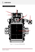
Page 3: ...1 2 3 5 4 6 Figure 1 1 1 Front view of PROTIUM 1000 CHAPTER 1 OVERVIEW 1 OVERVIEW 1 1 PROTIUM 1000 SYSTEM OVERVIEW ...

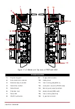
Page 4: ...g plate Bottom 4 Oxidant flow manifold 12 Load power connector XT 90 female 5 Oxidant blower 13 External power supply receptacle 6 Protective mask 14 Balance of plant BOP switch 7 Status LED 15 User mounting plate Top 8 ON OFF push button 16 H2 gas inlet connector 7 8 9 10 11 12 13 14 15 16 Figure 1 1 2 Bottom and Top views of PROTIUM 1000 CHAPTER 1 OVERVIEW ...

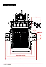
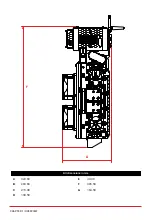
Page 5: ...CHAPTER 1 OVERVIEW 1 2 MECHANICAL DIMENSION D 8 R3 25 E C B Centre to Centre A ...

Page 6: ...All dimensions in mm A 323 60 E 40 00 B 283 60 F 395 50 C 215 00 G 164 50 D 100 50 CHAPTER 1 OVERVIEW F G ...

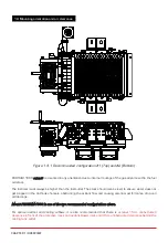
Page 7: ...idant flow and causing potential performance drop and cell damage Mount PROTIUM 1000 in one of the two recommended configurations above For optimal oxidant and cooling airflows it is also recommended that there is at least 15cm unobstructed clearance in front of the protective mask and oxidant blower inlet and 30cm unobstructed clearance behind the cooling fans outlet Figure 1 3 1 Recommended conf...

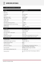
Page 8: ... min Gas tubing PU 8 x 5 5 Supply purge control Solenoid valves with integrated pressure sensor Stack leakage checks Automated via integrated pressure sensors Electronic Controller Processor board FEATHER V1 2 External power supply requirement 15 90V 150W max Weight including casing 680g Output connector XT 90 Warning protections Low voltage high low temperature high low pressure low battery stack...

Page 9: ...itioned PROTIUM 1000 at its Beginning of Life BOL Ambient temperature 24oC Relative humidity 60 H2 supply pressure 10psig Dead ended operation Balance of plant BOP powered by fuel cell Tcell at 1000W 66oC CHAPTER 2 SPECIFICATIONS 2 2 VI CURVE TEST CONDITIONS ...

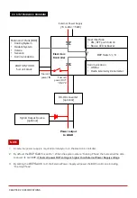
Page 10: ...ltage 3 By setting the BOP Switch to 0 the External Power Supply will power the BOP at all times including Running Phase Fuel cell power IN Power output to LOAD User Interface ON OFF push button Status LED Buzzer Communication USB or Radio telemetry transmitter External Power Supply 15 to 90V 150W Fuel cell power OUT 18 27V Hybrid Output Source optional DC DC converter optional NOTE PROTIUM 1000 f...

Page 11: ...l Set the parameters 57600 baud rate 8 data bit No parity 1 stop bit Reminder Ensure that all gas tubing and electrical wire connections are firm and secure PROTIUM 1000 is now ready to turn on CHAPTER 3 OPERATING PROCEDURES 3 OPERATING PROCEDURES 3 1 SETTING UP PROTIUM 1000 3 2 TURNING ON PROTIUM 1000 1 Turn on the external power supply Wait for 5s A welcome header should appear in the GUI LED wi...

Page 12: ...ax 2A second Constant Power Load 0W to 1000W max 100W second 2 During Running Phase the following live status of the fuel cell can be monitored from the GUI Parameters Description FCV FC voltage V FCA FC current A FCW FC power W Energy Energy delivered by the fuel cell during this operation Wh FCT1 FC temperature at location 1 C FCT2 FC temperature at location 2 C FAN Cooling fan duty cycle BLW Ox...

Page 13: ...tdown Initiated will appear in the GUI and PROTIUM 1000 will enter its Shutdown Phase The system is now OFF LED will blink at 60 on standby awaiting the next start up command 3 If you do not intend to restart the system soon turn OFF your Hydrogen gas supply and remove the Hydrogen gas tubing from the H2 gas inlet connector Caution some remaining gas in the tubing will be released into the atmosph...

Page 14: ...o decreasing power output equal Increase cooling fan speed by 5 manual control hyphen Decrease cooling fan speed by 5 manual control 0 Increase cooling fan speed by 1 manual control 9 Decrease cooling fan speed by 1 manual control Increase oxidant blower speed by 3 manual control Decrease oxidant blower speed by 3 manual control PROTIUM 1000 has several in built protections The LED will flash and ...

Page 15: ...ogen is not properly supplied within the stipulated time limit Check and ensure sufficient Hydrogen supply and correct delivery pressure Restart the system High Temperature Stack temperature is too high and the system will wait for 1min Error High Temperature Disconnect everything and wait for system to cool down and restart after 10min If the problem persists internal temperature sensor might hav...

Page 16: ...ry pressure Error Low H2 Supply Hydrogen supply pressure is too low Check and ensure sufficient Hydrogen supply and correct delivery pressure Restart the system High H2 Supply Pressure Hydrogen supply pressure is too high and the supply valve will be temporarily shut off LED will blink at 80 Reduce the delivery pressure Error High H2 Supply Pressure Hydrogen supply pressure is too high Check and e...

Page 17: ...ase Blink at 1Hz Meaning Power ON 10 5s after start up power is provided into the fuel cell controller LED will blink at 10 indicating that the system is ready to receive its start command Starting Phase 40 Executing Starting Phase procedures Running Phase 100 System in normal Running Phase Running Phase 80 System warning during Running Phase After shutdown 60 System off due to normal shutdown and...

Page 18: ...system enters Running Phase set constant voltage CV load of 18V and run the system for 1h The fuel cell should recover to its maximum rated power output PROTIUM 1000 is now ready for usual operation or can be stored again for future use CHAPTER 5 MAINTENANCE STORAGE 5 MAINTENANCE AND STORAGE 5 1 MAINTENANCE FOR PROTIUM 1000 5 2 STORAGE Keep PROTIUM 1000 in an open cool standard room temperature of...

Reviews: