Chapter 1: Module Overview
1-3
User’s Manual Pub. 0300322-01 Rev. A
-
Open circuit detection for current measurement on the 4-20 mA
range, voltage, and thermocouple measurements.
-
ADC Communication fault detection.
-
Channel bias adjustments for each channel.
-
An option to disable open-wire detection for volt, millivolt, and
thermocouple measurements.
All inputs have fault tolerance and ESD protection to avoid damage to circuitry
on the board. The modules use 50 VAC working Reinforced Insulation between
the inputs and the backplane, and low-level (10 VDC) channel-to-channel
isolation.
The 2085-IT8-SC module uses a 20-bit Sigma-Delta analog-to-digital converter
to achieve a 16-bit resolution. The 2085-IT16-SC module uses two 20-bit Sigma-
Delta analog-to-digital converters to achieve a 20-bit resolution. However, some
of the formats display the result in 16-bit resolution. The modules measure
thermocouple and CJ Sensors voltages and convert the results to a temperature
reading.
Each input channel is individually configurable via Rockwell-provided
Connected Component Workbench (CCW) software for the Micro850 and
Micro870 family controllers or with the Module Configuration Converter (MCC)
utility from Spectrum Controls, Inc.
The module is factory calibrated and tested before shipping. After installation,
the modules begin operation in a default, usable condition. During power startup,
all inputs are disabled and off until a valid configuration has been received.
The default configuration for the modules is for all channels enabled with the
Type J TC setting with the 17 Hz filter in Engineering ×1 units.
The module normally requires no further user intervention. However, if the
module experiences a hard fault condition, you may need to cycle power, or pull
the module from the rack.
Section 1.2
Input Specifications
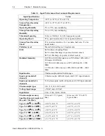
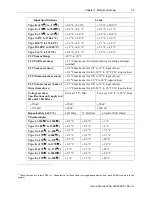
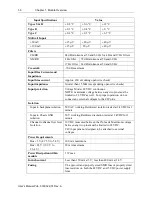
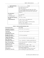
The 2085-IT8-SC/2085-IT16-SC modules have the following input
specifications.


