1-6
Chapter 1, Module Overview
User’s Manual Pub. 0300322-01 Rev. A
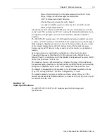
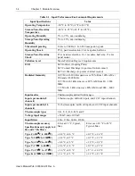
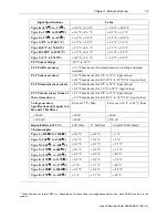
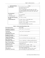
Input Specifications
Value
Types S & R
±0.4 °C
±0.6 °C
±12 °C
Type B
±0.3 °C
±0.4 °C
± 0 °C
Type C
±0.2 °C
±0.3 °C
±6.7 °C
Millivolt Inputs
±50 mV
±15 µV
±20 µV
±40 µV
±100 mV
±15 µV
20 µV
±40 µV
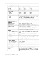
Filters
CMRR
84 dB minimum at 50 and 60 Hz for 4 Hz and 17 Hz filters
NMRR
4 Hz filter
72 dB minimum at 50 and 60 Hz
17 Hz filter
62 dB minimum at 50 and 60 Hz
Crosstalk
-70 dB maximum
Input Bias Currents and
Impedance
Input bias current
Approx. 100 uA during open wire check)
Input impedance
Greater than 15 MΩ (except during open wire checks)
Input protection
Voltage Mode ±28 VDC continuous.
NOTE: maximum voltage between any two pins must be
limited to 28 VDC as well. For proper operation, do not
connect any external voltages to the CJC pins.
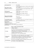
Isolation
Input to backplane isolation
50 VAC working Reinforced isolation tested at 2 kVDC for 1
minute
Input to Chasis GND
isolation
50 V working Reinforced isolation tested at 2 kVDC for 1
minute
Channel to channel low level
Isolation
10 VDC measured between the IN- leads. Maximum voltage
between any two pins must be limited to 28 VDC.
CJC input pins not designed to be attached to external
voltages.
Power Requirements
Bus +5 V (4.75 V to 5.4 V)
100 mA maximum
Bus +24 V (19.9 V to
26.4 V)
20 mA maximum
Power Dissipation within
module
1 W max
Inrush current
Less than 150 mA at 5 V; less than 400 mA at 24 V
Fusing
UL approved and properly sized SMD fuse or properly sized
fuse resistors on both the 24 VDC and 5 VDC power supply
lines.


