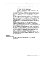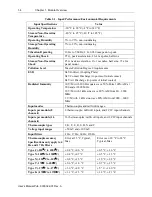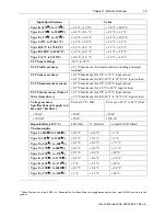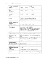
Chapter 2: Installation and Wiring
2-7
User’s Manual Pub. 0300322-01 Rev. A
Section 2.5
Field Wiring
Connections
Wiring Diagram
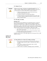
WARNING
Hazard of damage to the terminal connector.
The Spectrum Controls RTB hold down and terminal screws must be
tightened by hand using the guidelines. They must not be tightened using a
power tool. Use a screwdriver of 0.8 × 2 mm and tighten to no more than
0.25 N-m (2.2 in-lbs.) torque.
Failure to follow these guidelines may result in damage to your connector.
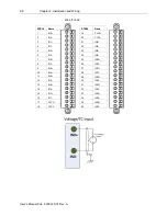
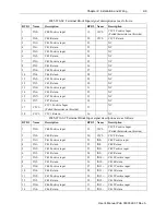
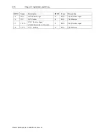
Wire the module using the following images, which explain the layout of each 2-
row, 18-pin terminal block, and the associated wiring diagrams for the various
input signals and the two modules.
RTB1#
Name
1
IN0+
2
IN0-
3
IN1+
4
IN1-
5
IN2+
6
IN2-
7
IN3+
8
IN3-
9
IN4+
10
IN4-
11
IN5+
12
IN5-
13
IN6+
14
IN6-
15
IN7+
16
IN7-
17
CJC1+
18
CJC1-
RTB2#
Name
19
CJC2+
20
CJC2-
21
NC
22
NC
23
NC
24
NC
25
NC
26
NC
27
NC
28
NC
29
NC
30
NC
31
NC
32
NC
33
NC
34
NC
35
NC
36
NC
2085-IT8-SC

