3-32
Chapter 3: Configuring the 2085-IT8-SC/IT-16-SC Using CCW
User’s Manual Pub. 0300322-01 Rev. A
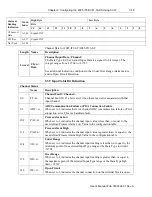
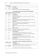
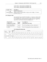
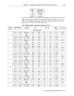
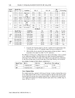
The Under Range and Over Range status bits are defined in the Channel Bit and
value allocation of the Input Table.
•
When the channel input reading is equal to or less than the minimum
point of the selected Input Type range, the Channel Under Range status
bit and the Channel Fault bit will be set. If the channel input reading
reaches the Input Type low limit or less, the channel input reading will
be clamped at that low limit value.
•
When the channel input reading is equal to or greater than the maximum
point of the selected Input Type range, the Channel Over Range status bit
and the Channel Fault bit will be set. If the channel input reading reaches
the Input Type high limit or greater, the channel input reading will be
clamped at the high limit value.
•
One possible condition that occurs is when the channel input reading is
equal to the limits of the signed 16-bit Data Type before reaching the
minimum or maximum point of the selected Input Type range. This
condition can happen when the Type B or C TC is selected for
measurement in Fahrenheit units. The channel Under/Over range status
bits will be set, and the channel input reading will be clamped at the Data
Type limits.
•
The channel Under or Over range status bits will be cleared when the
channel input reading is greater than the minimum point, or less than, the
maximum point of the selected Input Type range.
•
The channel Under or Over range status bits will also be cleared when
the channel input reading is greater or less than the low or high limit of
the Data Type if the minimum or maximum point of the selected Input
Type range is beyond the data limits.
Section 3.8 ADC Alarm
When each input channel is acquiring its channel data in sequence on the
corresponding ADC measurement circuit, to ensure the validity of the data
reading, the ADC and PGA IDs and the signal reading are validated for reporting
potential acquisition failure in time.
If a communication failure occurs, the channel ADC Fault bit and the Channel
Fault bit will be set in the input table. This can happen when the ESD
environment is out of the hardware specification tolerance or the hardware
connection on the ADC and PGA component is damaged.
To clear the fault bit, cycle power the module. If still not cleared, you will need
to send the module back to Spectrum Controls for further inspection.
Section 3.9 Data Not Ready Alarm
The Data Not Ready bit in the input table is useful for letting you know you
should avoid monitoring the channel input data until the initial temperature
sampling on the CJ Sensor is completed.
Whenever the module is powered up or any of the CJ Sensors are connected on
the terminal block, the CJ Sensor needs to collect the initial 100 samples. If any
input channel is configured to run thermocouple measurement with any CJC
profile option enabled, the channel DNR bit and the Channel Fault bit will be set
in the input table. Once the sample collection is completed and the CJ Sensor has


