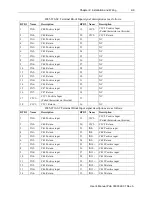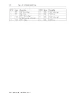
1-10
Chapter 1, Module Overview
User’s Manual Pub. 0300322-01 Rev. A
Table 1-4 LED Status Indicators
Indicator
State
Description
Module OK
LED Status
Off
No power applied to device or the module may have
failed to pass its self-test.
Solid
Green
RUN mode. Module has power and passed self-test.
No action is required.
Blinking
Green
LED blink status:
1. Internal use only.
2. Internal use only.
3: Internal use only.
4: Internal use only.
5: Indicates ADC communication error.
6: Indicates Watchdog reset.
Section 1.5
System
Overview
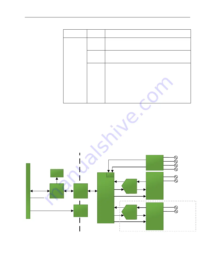
The 2085-IT8/IT16-SC module is expected to operate indefinitely. It does not
require periodic maintenance or calibration. The module communicates to the
controller through the bus interface. The module also receives 5 VDC and 24
VDC through the bus interface.
Block diagram:
Isolator
Isolated
DC-DC
Converter
Inx+
Inx-
CJC1+
CJC1-
Backplane
ASIC
Backplane
Communication
RTB pins
.
.
.
x8
channels
Processor
50VAC
Working
Reinforced
Isolation
5V DC
24V DC
(used by backplane
circuitry)
Status
Indicator
A/D
20
85
B
ac
kp
la
n
e
CJC2+
CJC2-
Inx+
Inx-
8-Input
Channels
ESD
Protection,
Channel
Multiplexing,
& Signal
Conditioning
.
.
.
x8
channels
Installed on
IT16 only
Signal
Conditioning
8-Input
Channels
ESD
Protection,
Channel
Multiplexing,
& Signal
Conditioning
A/D
Converter
A/D
Converter

