2-4
Chapter 2: Installation and Wiring
User’s Manual Pub. 0300322-01 Rev. A
2.4.1
Minimum Spacing
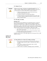
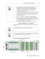
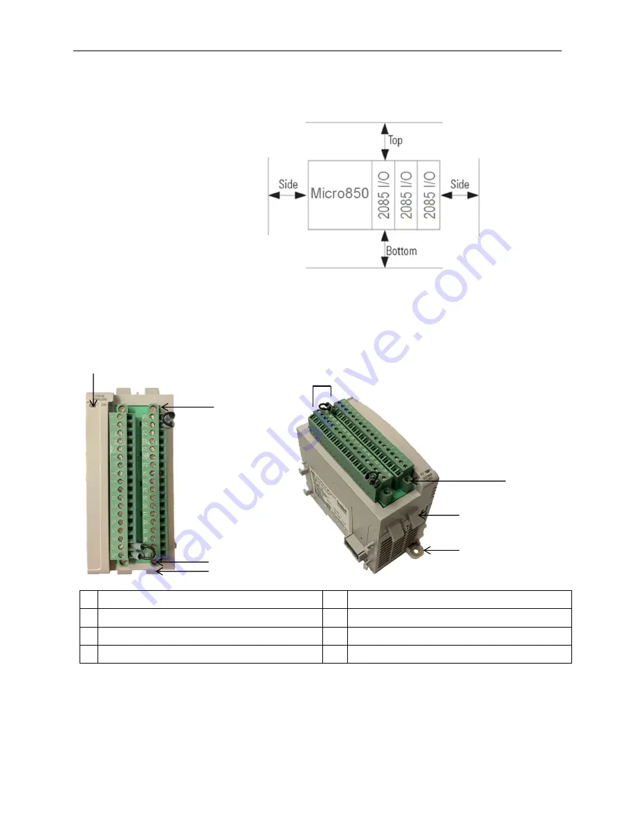
Maintain spacing from enclosure walls, wire ways, adjacent equipment, etc.
Allow 50.8 mm (2 in.) of space on all sides for adequate ventilation, as shown:
2.4.2
Parts List
Your package contains one 2085-IT8-SC or 1 2085-IT16-16-SC Channel
Thermocouple and Millivolt Analog Input Module, and one Quick Start Guide.
2.4.3
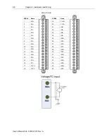
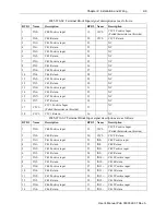
Module Description
Description
Description
1 Mounting screw hole/mounting foot
4
Module interconnect latch
2 Removable Terminal Block (RTB)
5
DIN rail mounting latch
3 RTB hold down screws
6
I/O Status LED
You can choose to wire the expansion I/O module before installing it next to the
controller or wire it once the module is secured in place.
Place the module next to the controller against the panel where you are mounting
it. Make sure the controller and module are spaced properly.
3
2
4
1
6
5
3
3


