3-30
Chapter 3: Configuring the 2085-IT8-SC/IT-16-SC Using CCW
User’s Manual Pub. 0300322-01 Rev. A
•
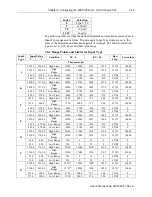
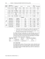
An open circuit condition may also be triggered by feeding channel input
voltage or temperature well beyond the defined limit values indicated in
the Range Points and Limits table.
•
To get the most accurate measurement results from 2085-IT16-SC
modules, please follow these tips:
-
In applications that need open circuit detection, do not tie signals
together between two terminal block banks (for instance IN0-
and IN14-).
-
Turn off open circuit detection for both terminal blocks in
applications that need to tie signals together between terminal
blocks (like an external common ground that is needed to tie
together terminals in voltage measurement applications).
-
Turn off open circuit detection function on the channels that are
using a sensor that has more than 80 KOhm output impedance.
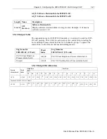
3.6.10
Process Alarm and Latching
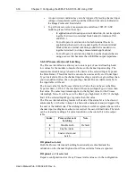
The Process Alarm feature allows you to enter a pair of user-defined high and
low values for the module to monitor between the channel input reading. The
maximum enterable range is based on the limits of the selected Input Type and
the Data Format. This alarm feature can also be used as an Over or Under Input
Type Limit alarm. Once the channel input reading is equal to or greater/less than
your user-defined value, the corresponding channel Process Alarm status bit in
the input table will be set.
The lowest value for the Process Alarm Low Value that can be set is the Data
Type low limit, -32768, if the low limit of the selected Input Type is lower than
that value. The same requirement applies to the highest value for the Process
Alarm High Value. It will be set to the Data Type high limit, +32767, if the high
limit of the selected Input Type is greater than that value.
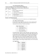
The Process Alarm Latching feature will decide if the status bit is to be cleared
automatically or whether to keep it latched until a manual cleanup is triggered by
the user or the ladder code. The latching feature is useful to capture whenever the
channel input reading has reached, or exceeded, the user-defined value. The latch
can be cleared by making a bit value transition on the control bit in the output
table.
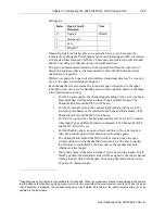
Index
Process Alarm &
Latching
Note
0
Disable Both
Default
1
Enable Alarm
2
Enable Alarm and
Latch
If Option 0 selected,
Both the Process Alarm and Latching functionality are disabled and the
validation on the channel High and Low Process Alarm Values is ignored.
If Option 1 or 2 is selected,
Report a configuration error if any Process Alarm value set in the configuration

