background image

Page 15

For technical questions, please call 1-888-866-5797.
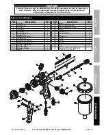
Item 64823 64824 
        

NOTICE

Clean the Spray Gun and Cup IMMEDIATELY after EVERY use and when it will be idle for more 

than 30 minutes.  Delayed or inadequate cleaning will permanently clog the Spray Gun. 

DO NOT USE LATEX PAINT IN THIS SPRAY GUN.

S

AFETY

Op

ERA

TION

M

AINTENANCE

S

ET

up

After Every use

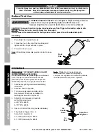
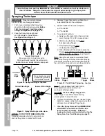
WARNING! TO pREVENT FIRE,  
IF A FLAMMABLE SOLVENT NEEDS TO BE uSED,  
ADHERE TO THE FOLLOWING:

a. 

Follow solvent manufacturer’s clean up 
instructions and safety precautions.

b. 

Flush Spray Gun a full hose 
length from air compressor.

c. 

If collecting flushed solvents in 
metal container, transfer to nonmetal 
container, and flush metal container.

d. 

Work far away from any ignition 
sources in a vapor free area.

e. 

Keep class ABC fire extinguisher nearby.

Solvent Selection

Follow the paint and solvent manufacturer’s recommendations for cleaning, solvent type, and disposal.

post-Cleaning

NOTICE:  Do not immerse Spray Gun Body in 
solvent.  Do not allow solvent to enter the air inlet. 

1.  Use solvent recommended by paint manufacturer. 
2.  Designate a container for spent solvent.
3.  Remove Cup’s Lid.  Carefully scrape paint out 

of Cup and dispose of excess paint properly.

4.  Add 1/4 cup of solvent (sold separately) to 

Cup.  Replace Lid and Close Air Vent, then 
shake Spray Gun for several seconds.

5.  Remove Lid, pour solvent into spent solvent 

container and wipe away any paint residue 
from Cup and Lid with clean cloth.

6.  Add 1/4 cup of solvent to Cup.  Replace 

Lid and pull out Air Vent to open.

7.  Open Fluid Control Knob and Fluid Lock Nut 

(counterclockwise) until four threads are 
showing.  Turn Fluid Control Knob Lock clockwise 
until it stops against the Spray Gun body.

8.  Open Air Control Knob fully.
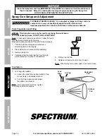
9.  Point Spray Gun at interior side of spent solvent 

container.  Depress Trigger and slightly shake 
Spray Gun while spraying solvent into the 
container.  Once the Cup is empty, repeat the 
process until the solvent comes out clean.

10.  Disconnect Spray Gun from the air source.  
11.  After disconnecting, point the Spray Gun into 

the spent solvent container and depress the 
Trigger again to make sure no air remains.

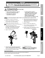
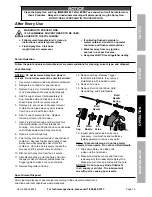
12.  Remove Regulator and Cup.

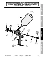
13.  Remove Air Cap. Depress Trigger 

to retract Fluid Needle, then remove 
Fluid Nozzle with included wrench.  

14.  Remove Air Valve.
15.  Remove Fluid Control Knob, Fluid 

Need Spring, and Fluid Needle.

Air 

Cap 

Fluid 

Nozzle

Air 

Valve

Fluid 

Needle

Fluid 

Needle 

Spring

16.  Inspect parts and soak in solvent as 

necessary.  Use brushes and toothpicks 
(sold separately) to remove any paint.

Note:


To prevent damage, do not use metal 

objects to clean parts.  Do not bend Fluid Needle.

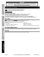
17.  Wipe down Spray Gun Body with 

a clean cloth and solvent.

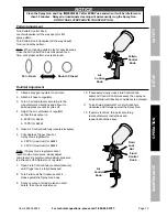
18.  Make sure all parts are dry and free from 

residual paint, then reassemble Spray Gun.  
Make sure Air Valve’s pin slides into top hole. 

NOTICE:


Do not use any kind of lubricant 

in air supply or air inlet.  The lubricant will 
mix with paint, causing poor results.

Spent Solvent Disposal

After cleaning, dispose of spent solvent according to the solvent manufacturer’s 
directions and local hazardous waste standards.

Summary of Contents for 64823

Page 1: ...ssing or broken please call 1 888 866 5797 as soon as possible Copyright 2018 by Harbor Freight Tools All rights reserved No portion of this manual or any artwork contained herein may be reproduced in any shape or form without the express written consent of Harbor Freight Tools Diagrams within this manual may not be drawn proportionally Due to continuing improvements actual product may differ slig...

Page 2: ...tion which if not avoided could result in death or serious injury Indicates a hazardous situation which if not avoided could result in minor or moderate injury Addresses practices not related to personal injury IMpORTANT SAFETY INSTRuCTIONS INSTRuCTIONS pERTAINING TO A RISK OF FIRE ELECTRIC SHOCK OR INJuRY TO pERSONS The warnings and precautions discussed in this manual cannot cover all possible c...

Page 3: ...lways wear eye protection Wear ANSI approved safety goggles Tool use and Care a Do not force the tool Use the correct tool for the application The correct tool will do the job better and safer at the rate for which the tool is designed b Disconnect the tool from the air source before making any adjustments changing accessories or storing the tool Such preventive safety measures reduce the risk of ...

Page 4: ...rior to using the tool that the air source has been adjusted to the rated air pressure or within the rated air pressure range b Never use oxygen carbon dioxide combustible gases or any bottled gas as an air source for the tool Such gases are capable of explosion and serious injury to persons SAVE THESE INSTRuCTIONS Symbol Definitions Symbol property or Statement pSI Pounds per square inch of press...

Page 5: ... coating manufacturer as needed regarding potential chemical reactions 5 RISK OF INJECTION Do not point spray gun at any person or any part of the body In case of skin injection seek medical attention immediately 6 Industrial applications must follow OSHA requirements 7 Spraying hazardous materials may result in serious injury or death Do not spray pesticide acid corrosive material fertilizer or t...

Page 6: ...Incorporate a filter regulator with pressure gauge in line shutoff ball valve and quick coupler for best service as shown on Figure A on page 7 An in line shutoff ball valve is an important safety device because it controls the air supply even if the air hose is ruptured The shutoff valve should be a ball valve because it can be closed quickly NOTICE Do not use an automatic oiler system or add oil...

Page 7: ...NANCE SETup Figure A portable Air Supply Setup D B A F G B C E Non lubricated Tools Description Function A Shutoff Ball Valve Isolates sections of system for maintenance B Air Hose Connects air to tool D Filter Prevents dirt and condensation from damaging tool or workpiece E Compressor Regulator Adjusts air pressure to tool F Coupler and Plug Provides quick connection and release C Air Cleaner Dry...

Page 8: ...fore set up or use of this product Inspect tool before use looking for damaged loose and missing parts If any problems are found do not use tool until repaired Workpiece and Work Area Set up 1 Designate a work area that is clean and well lit The work area must not allow access by children or pets to prevent distraction and injury 2 Route the air hose along a safe path to reach the work area withou...

Page 9: ...inutes Delayed or inadequate cleaning will permanently clog the Spray Gun DO NOT USE LATEX PAINT IN THIS SPRAY GUN SAFETY OpERATION MAINTENANCE SETup Components and Controls Air Vent not shown Air Cap Trigger Lock Ring Fluid Nozzle Fluid Filter Air Valve Fluid Control Knob Fluid Lock Nut Fluid Needle Gun Body Fluid Needle Spring pattern Control Knob Air Inlet Air Control Knob Cup ...

Page 10: ...n until the Cup is securely in place 3 Pull out Air Vent to open Note When Spray Gun is idle push in Air Vent to close Fluid Filter Air Vent Air Adjustment WARNING TO pREVENT SERIOuS INJuRY FROM ACCIDENTAL OpERATION Do not install a female quick coupler on the tool Such a coupler contains an air valve that will allow the air tool to retain pressure and operate accidentally after the air supply is ...

Page 11: ...lace Lid and pull out Air Vent to open Note When Spray Gun is idle push in Air Vent to close 4 Open Fluid Control Knob and Fluid Lock Nut counterclockwise until four threads are showing Turn Fluid Lock Nut clockwise until it stops against the Spray Gun body 5 Open Air Control Knob fully PSI Bar Fluid Control Knob Fluid Lock Nut 6 Point Spray Gun at interior side of spent solvent container Depress ...

Page 12: ...rborne and solvent based paints DO NOT uSE LATEX pAINT Note Proper paint mixture is essential Follow the paint manufacturer s directions for thinning Most paints will spray easily if they are thinned properly 1 Thin the paint according to manufacturer s directions and mix thoroughly 2 Place Spray Gun in stand sold separately 3 Remove Cup s Lid 4 Carefully strain the paint into the Cup through a pa...

Page 13: ...ild up pressure until it cycles off 4 Adjust the air compressor s regulator so that the air output is a 60 PSI for 64823 b 70 PSI for 64824 5 Open Air Control Knob fully counterclockwise 6 Fully depress Trigger then set Spray Gun s regulator to a 28 PSI maximum for 64823 b 35 PSI maximum for 64824 Note If Spray Gun s regulator cannot reach maximum pressure slowly adjust compressor s regulator unti...

Page 14: ...ger fully and move Spray Gun in parallel strokes to the workpiece 4 Keep the distance from the workpiece a 6 for 64823 b 7 for 64824 5 To avoid paint build up a Apply two thin coats rather than one thick coat Overlap 1 3 to 1 2 on second coat b Start moving the Spray Gun before fully depressing Trigger c Fully depress Trigger before contacting the workpiece d When finished with the stroke release ...

Page 15: ...th 6 Add 1 4 cup of solvent to Cup Replace Lid and pull out Air Vent to open 7 Open Fluid Control Knob and Fluid Lock Nut counterclockwise until four threads are showing Turn Fluid Control Knob Lock clockwise until it stops against the Spray Gun body 8 Open Air Control Knob fully 9 Point Spray Gun at interior side of spent solvent container Depress Trigger and slightly shake Spray Gun while sprayi...

Page 16: ...r cleaning procedures TO pREVENT SERIOuS INJuRY FROM TOOL FAILuRE Do not use damaged equipment If abnormal noise vibration or leaking air occurs have the problem corrected before further use Inspection Note These procedures are in addition to the regular checks and maintenance explained as part of the regular operation of the air operated tool BEFORE EACH uSE inspect the general condition of the t...

Page 17: ...acturer s instructions 3 Increase air pressure within the Working Air Pressure Light center pattern 1 High air pressure 2 Fluid Knob not open enough 3 Pattern Knob open too far 1 Reduce air pressure 2 Open Fluid Knob 3 Partially close Pattern Knob Heavy top bottom pattern 1 Air Cap plugged 2 Air Cap loose 3 Dried paint on Fluid Nozzle 1 Clean Air Cap 2 Clean and tighten Air Cap 3 Use a nonmetallic...

Page 18: ... Fluid Nozzle Air Leaking from Air Cap Buildup on Air Valve Clean Air Valve Follow all safety precautions whenever diagnosing or servicing the tool Disconnect air supply before service pLEASE READ THE FOLLOWING CAREFuLLY THE MANUFACTURER AND OR DISTRIBUTOR HAS PROVIDED THE PARTS LIST AND ASSEMBLY DIAGRAM IN THIS MANUAL AS A REFERENCE TOOL ONLY NEITHER THE MANUFACTURER OR DISTRIBUTOR MAKES ANY REPR...

Page 19: ...cription Qty 1 Air Cap 1 2 Fluid Nozzle 1 3 Air Valve 1 4 Gun Body 1 5 Fluid Inlet 1 6 Needle Packing 1 7 Fluid Spring 1 8 Needle Packing Nut 1 9 Fluid Needle 1 10 Fluid Needle Spring 1 11 Fluid Control Knob Set 1 12 Air Valve Lock Seat 1 13 Air Valve Shaft 1 14 Air Valve Gasket 1 15 Spring 1 part Description Qty 16 Screw 1 17 Fan Control Assembly 1 18 Pattern Adjustment Knob 1 19 Screw 1 20 Air I...

Page 20: ...lusion or limitation of incidental or consequential damages so the above limitation of exclusion may not apply to you THIS WARRANTY IS EXPRESSLY IN LIEU OF ALL OTHER WARRANTIES EXPRESS OR IMPLIED INCLUDING THE WARRANTIES OF MERCHANTABILITY AND FITNESS To take advantage of this warranty the product or part must be returned to us with transportation charges prepaid Proof of purchase date and an expl...

Reviews: