22
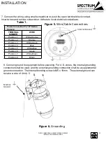
7. Connect the wiring using small screwdriver to push the open terminal block contact.
Insert wires and remove screwdriver. Adhere to local electrical codes/laws.
D201-1-Q6055 REV 4 105607312018 D SERIES
INSTALLATION MANUAL REV-1
Power Connection To "D" Series
Camera
TERMINAL
NUMBER
WIRE
Position - 1
White-Orange
Position - 2
Orange
Position - 3
White-Green
Position - 4
Blue
Position - 5
White-Blue
Position - 6
Green
Position - 7
White-Brown
Position - 8
Brown
Table 1.
Figure 5.
Wire/Cable Connections
INSTALLATION
External
Ground
Internal Ground
Figure 6.
Grounding
8. Connect ground to equipment before powering. For U.S. zones, the internal grounding
connection shall be used, and the external grounding connection shall be a supplemental
ground connection. The internal bonding screw is M5 x 15mm. The external ground can
receive a wire of 4 mm. 5


