background image

Dismantling:

It is not recommended to open the main camera housing.  All repairs of explosion-proof 

equipment must be made according the specified criteria of IEC/EN 60079-19 rule by qualified 

personnel, having knowledge concerning electrical equipment for potentially explosive areas 

containing gas and/or dust.  Qualified personnel must have knowledge regarding the types of 

explosion protection.

Maintenance:

The maintenance must be realized in accordance with IEC/EN 60079-17 and/or in accordance 

with the national requirements.   Contact Spectrum Camera for training program to properly 

open and close the main camera housing.

Cleaning lens-

Washdown dome with water first to avoid partials scratching the surface. Clean 

lens with damp microfiber cloth with mild dish soap and water. Lastly, apply coating of Repel (by 

Unelko corporation) surface cleaner.  Never use harsh chemicals or abrasive towels.
Replacing the battery- The Axis Q6055-E product uses a *Panasonic 3.0 V BR2032 lithium 

battery Lithium primary battery composed of cathode from carbon monofluoride anode from 

lithium and electrolyte from organic solvent and lithium salt as the power supply for its internal 

real-time clock (RTC). Under normal conditions this battery will last for a minimum of five years. 

Low battery power affects the operation of the RTC, causing it to reset at every power-up. When 

the battery needs replacing, a log message will appear in the product’s server report. For more 

information about the server report, see the product´s setup pages or contact Spectrum support. 

The battery should not be replaced unless required, but if the battery does need replacing, 

contact Spectrum support at www.spectrumcamera.com/support for assistance or To obtain 

assistance, please go to 

https://www.axis.com/support. 

This battery is not field replaceable*.

27

DISMANTLING & MAINTENANCE

105607312018 D201-x-Q6055-E  

INSTALLATION MANUAL REV-1

Summary of Contents for D201-S-Q6055-E-BD

Page 1: ...D201 S Q6055 E BD Explosion Camera Proof Network Camera Installation Manual 1 105607312018 D201 x Q6055 E INSTALLATION MANUAL REV 1 ...

Page 2: ...Thispageintentionallyleftblank 2 105607312018 D201 x Q6055 E INSTALLATION MANUAL REV 1 ...

Page 3: ...Solutions LLC acknowledges all trademark s and the rights of the trademark s owned by the company referred to herein Release Date 08 30 2018 Document Name D201 S Q6055 E BD Copyright 2018 by Spectrum Camera Solutions LLC All rights reserved Revision Record Rev Description Date 0 Initial Release Aug 30 2018 1 Updated Oct 10 2018 3 105607312018 D201 x Q6055 E INSTALLATION MANUAL REV 1 ...

Page 4: ...a Solutions Inc exercising maximum possible legal action against all persons and or organizations involved Disclaimer Spectrum Camera Solutions LLC makes no representations or warranties with respect to the contents hereof Further Spectrum Camera Solutions LLC reserves the right to revise this publication and to make changes in the content hereof without obligation to notify any person or organiza...

Page 5: ...8 STANDARDS AND CERTIFICATIONS 9 DOCUMENT SYMBOLS 10 HOW TO USE THIS MANUAL 11 GENERAL SAFETY AND OPERATING INFORMATION 12 14 SPECIFICATIONS 15 17 INSTALLATION 18 24 DIMENTIONAL GENERAL ASSEMBLY 25 HARDWARE BOM 26 DISMANTLING MAINTENANCE 27 MOUNTING OPTIONS 28 33 105607312018 D201 x Q6055 E INSTALLATION MANUAL REV 1 ...

Page 6: ...increases safety by lessening the potential for mismatched hazardous rated components Additionally the D Series are constructed with a proprietary explosion resistant polymer blend offering maximum clarity and enhance optical performance To enhance optical performance the explosion proof lens is equipped with our Virtual Wiper Nano Technology The series are available in anodized aluminum or 316L S...

Page 7: ...1 A Aluminum Housing with SS 316L Dome Ring 1 S Stainless Steel 316L Housing C Internal Equipment Part Number from Manufacturer BD Optional Breather drain model Internal components and D Series must be approved by Spectrum Internal Equipment Manufacturer Code below Must be approved and verified by Spectrum Models supplied with Breather Drains will have IP66 ingress protection level CODE XX Manufac...

Page 8: ...Labels 8 BREATHER DRAIN MODEL BREATHER DRAIN MODEL 105607312018 D201 x Q6055 E INSTALLATION MANUAL REV 1 ...

Page 9: ... s instructions to reduce the potential of an electrostatic charging hazard on the surface of the equipment in Group II and III environments The equipment meets the requirements according to the low level risk of mechanical danger Therefore the equipment shall be located and installed such that the risk of impact or other mechanical damage is reduced or avoided NOTE Use a clean cloth dampened with...

Page 10: ...N Risk of electric shock or high temperature parts may result in injury if proper precautions are not taken NOTE Emphasizes important or essential information Locating Information NOTE In the interest of completeness manuals and drawings included with the system may provide information pertaining to options not included with your equipment Information in application notes supersedes general inform...

Page 11: ...d FM certificates for any Special Conditions of Use If the sign X is placed after the certificate number it indicates that the equipment or protective system is subject to special conditions for safe use specified in the schedule of the certificate NOTE Review all material and safety information in this manual and install in accordance with this document and all other applicable ATEX CSA IECEx NEC...

Page 12: ...orn when installing and servicing any part of electrical equipment Hot components should be allowed to cool before servicing if possible Other appropriate equipment or clothing must be used as required by the type of work performed All applicable regulations and procedures must be followed for the work performed Before beginning any work on the equipment carefully consider all the potential hazard...

Page 13: ...tructure CAUTION The electrical cover should never be removed unless power is removed for at least 5 minutes from the unit or the area is known not to contain explosive materials 13 WARNING The product shall be installed by a trained professional The product shall be used in compliance with local laws and regulations Store the product in a dry and ventilated environment Avoid exposing the product ...

Page 14: ... properties of terminal housing compartment The connection to the external circuits must be realized by cable glands or pipe fittings covered by a separate certificate s If a cable gland is not used or an entry is open the entry must be closed by a stopping plug covered by a separate certificate The diameter of the cable gland is cylindrical ISO M20 x 1 5 This equipment can be used with different ...

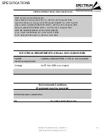
Page 15: ...T6 Type 4X IP66 67 Ta 20 C to 55 C Class I Zone 1 AEx Ex db IIB H2 T6 Gb Ta 20 C to 55 C Type 4X IP66 Zone 21 AEx Ex tb IIIC T85 C Db Ta 20 C to 55 C Type 4X IP66 CERT NO FM18ATEX0057X IECEx FMG 18 0020X II 2 G Ex db IIB H2 T6 Gb Ta 20 C to 55 C IP66 II 2 D Ex tb IIIC T85 C Db Ta 20 C to 55 C IP66 ELECTRICAL REQUIREMENTS of Model D201 S Q6055 E BD POWER INPUT CONSUMPTION CAMERA CONSUMPTION TYPICAL...

Page 16: ...roper installation of its products sold and assumes no liability for injury from use or misuse or improper installation of its products or attached products D201 S Q6055 E BD Explosion Proof Camera Hazardous Area Voltage Material Model Number IEEE 802 3bt PoE 60W PoE Midspans PoE Injectors 316L STAINLESS STEEL D201 S Q6055 E BD 16 SPECIFICATIONS Power Source Specification For D201 S Q6055 E BD AXI...

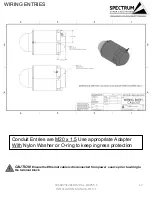
Page 17: ...x 1 5 Use appropriate Adapter With Nylon Washer or O ring to keep ingress protection CAUTION Ensure the Ethernet cable is disconnected from power source prior to wiring to the terminal block 105607312018 D201 x Q6055 E INSTALLATION MANUAL REV 1 ...

Page 18: ...ock washers supplied on camera 2 Make sure threads on camera and M10x 1 5 are free of dirt and debris Place mount on camera and align holes and tighten bolts 3 Attach the camera with wall mount to mounting surface Use only installation methods and materials capable of supporting four times the maximum specified load of the system Figure 1 wall bracket installation INSTALLATION 105607312018 D201 x ...

Page 19: ...ble gland and seal using the recommended gland installation practices There are two conduit entries on models without the BD Breather drain option Figure 2 Removing D1005 terminal cap Conduit Entries are M20 x 1 5 Use appropriate Adapter with Nylon Washer or O ring to keep ingress protection follow guidelines of the manufacturer of gland or adapter INSTALLATION 105607312018 D201 x Q6055 E INSTALLA...

Page 20: ...O ring to keep ingress protection Example of CMP M20 to 3 4NPT adapter with Nylon Washer INSTALLATION CAUTION Ensure the Ethernet cable is disconnected from power source prior to wiring to the terminal block Figure 3 Figure 4 105607312018 D201 x Q6055 E INSTALLATION MANUAL REV 1 ...

Page 21: ...to local electrical codes laws Power Connection To D Series Camera TERMINAL NUMBER WIRE Position 1 White Orange Position 2 Orange Position 3 White Green Position 4 Blue Position 5 White Blue Position 6 Green Position 7 White Brown Position 8 Brown Table 1 Figure 5 Wire Cable Connections INSTALLATION 105607312018 D201 x Q6055 E INSTALLATION MANUAL REV 1 ...

Page 22: ...round can receive a wire of 4 mm The user installer must connect the internal and external earthing before powering STP cable connection with earthing in camera junction box The earth wire is the screen of the cable to be isolated in the wiring terminal junction box size Green Thread forming Bonding Screw M5 x 15mm 22 External Ground Internal Ground Figure 6 Grounding INSTALLATION 105607312018 D20...

Page 23: ... M5 supplied Hex tool to tighten by turning clockwise until hand tight and gasket is seated 12 In the following order install D2005 housing retainer clip wedge lock washers and nut Ground lug is at bottom of thread adapter See figure 8 9 Figure 7 Installing D1005 cap Figure 8 Retaining clip order Figure 9 Final assembly INSTALLATION 105607312018 D201 x Q6055 E INSTALLATION MANUAL REV 1 ...

Page 24: ...h UV exposure 14 Apply power For internal equipment startup procedures setting changes and troubleshooting guides reference the camera manufacturer s manual included with the D Series Cameras If the included copy is lost please contact https www spectrumcamera com support or To obtain assistance please go to https www axis com support INSTALLATION 105607312018 D201 x Q6055 E INSTALLATION MANUAL RE...

Page 25: ...Dimensional General Assembly 25 105607312018 D201 x Q6055 E INSTALLATION MANUAL REV 1 ...

Page 26: ...3 2 5 1 QTY 1 EXTERNAL GROUND LUG 2 QTY 3 M10 X 1 5 18 8 BOLT 3 4 SETS WEDGE LOCK WASHER 4 QTY 1 D2005 Z CLIP 5 SD WM WALL MNT NOT INCLUDED 6 M10X1 25 M10X1 5 ADAPTER 6 105607312018 D201 x Q6055 E INSTALLATION MANUAL REV 1 ...

Page 27: ...r Never use harsh chemicals or abrasive towels Replacing the battery The Axis Q6055 E product uses a Panasonic 3 0 V BR2032 lithium battery Lithium primary battery composed of cathode from carbon monofluoride anode from lithium and electrolyte from organic solvent and lithium salt as the power supply for its internal real time clock RTC Under normal conditions this battery will last for a minimum ...

Page 28: ...SD WM WALL MOUNT 28 105607312018 D201 x Q6055 E INSTALLATION MANUAL REV 1 ...

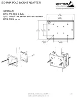
Page 29: ...SD PMA POLE MOUNT ADAPTER 29 HARDWARE QTY 4 7 8 20 18 8 Bolts QTY 2 12in all thread with nuts and washers QTY 2 A1612 sides 105607312018 D201 x Q6055 E INSTALLATION MANUAL REV 1 ...

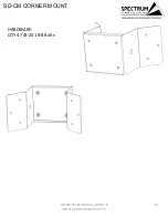
Page 30: ...SD CM CORNER MOUNT 30 HARDWARE QTY 4 7 8 20 18 8 Bolts 105607312018 D201 x Q6055 E INSTALLATION MANUAL REV 1 ...

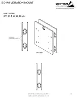
Page 31: ...SD VM VIBRATION MOUNT 31 HARDWARE QTY 4 7 8 20 18 8 Bolts FRONT 105607312018 D201 x Q6055 E INSTALLATION MANUAL REV 1 ...

Page 32: ...SD SO STANDOFF MOUNT 32 HARDWARE QTY 4 7 8 20 18 8 Bolts FRONT BACK 105607312018 D201 x Q6055 E INSTALLATION MANUAL REV 1 ...

Page 33: ...ASSEMBLY MOUNTS 33 SD CM SD PMA SD CM SD VM SD SO SD PMA 105607312018 D201 x Q6055 E INSTALLATION MANUAL REV 1 ...

Page 34: ... with EN 60950 or EN 62368 complying with the IEEE 802 3af 802 3at 802 3at or 802 3bt PoE Power over Ethernet standard 57Vdc max Voltage and wattage shall not exceed the maximum tested configuration of 57Vdc 60W The D Series Network Ethernet Cameras are rated for use in an ambient temperature range of 20 C to 55 C and are IP66 67 IP67 is not applicable when supplied with optional breather drain Th...

Page 35: ...ith EN 60950 or EN 62368 complying with the IEEE 802 3af 802 3at 802 3at or 802 3bt PoE Power over Ethernet standard 57Vdc max Voltage and wattage shall not exceed the maximum tested configuration of 57Vdc 60W The D Series Network Ethernet Cameras are rated for use in an ambient temperature range of 20 C to 55 C and are IP66 67 IP67 is not applicable when supplied with optional breather drain The ...

Reviews: