background image

12

SPEKTRUM DX3E USER GUIDE

3.  Q: I’ve heard that the DSM system is less tolerant of 

low voltage. Is this correct?

A:  All DSM receivers have an operational voltage range 

of 3.5 to 9 volts. With most systems this is not a 

problem as in fact most servos cease to operate at 

around 3.8 volts. When using multiple high-current 

draw servos with a single or inadequate battery/ 

power source, heavy momentary loads can cause the 

voltage to dip below this 3.5-volt threshold causing 

the entire system (servos and receiver) to brown 

out. When the voltage drops below the low voltage 

threshold (3.5 volts), the DSM receiver must reboot 

(go through the start up process of scanning the 

band and finding the transmitter) and this can take 

several seconds.

4.  Q: Sometimes my receiver loses its bind and won’t 

connect, requiring rebinding. What happens if the 

bind is lost in use?

A:  The receiver will never lose its bind unless it’s 

instructed to. It’s important to understand that during 

the binding process the receiver not only learns the 

GUID (code) of the transmitter but the transmitter 

learns and stores the type of receiver that it’s bound 

to.

If the system fails to connect, the following more than 

likely may have occurred:

•  The transmitter is near conductive material 

(transmitter case, truck bed, etc.) and the reflected 

2.4GHz energy is preventing the system from 

connecting. (See #2 on this page)

TIPs on usIng 2.4ghz sysTems

Your DSM equipped 2.4GHz system is intuitive to 

operate, functioning nearly identically to FM systems. 

Following are a few common questions from customers.

1.  Q: Which do I turn on first, the transmitter or the 

receiver?

A:  It doesn’t matter, although it is suggested to turn the 

transmitter on first. If the receiver is turned on first, 

all channels will be driven to the failsafe position 

set during binding. When the transmitter is then 

turned on the transmitter scans the 2.4GHz band and 

acquires an open channel. Then the receiver that was 

previously bound to the transmitter scans the band 

and finds the GUID (Globally Unique Identifier code) 

stored during binding. The system then connects and 

operates normally. If the transmitter is turned on first, 

the transmitter scans the 2.4GHz band and acquires 

an open channel. When the receiver is turned on, 

the receiver scans the 2.4GHz band looking for the 

previously stored GUID. When it locates the specific 

GUID code and confirms uncorrupted repeatable 

packet information, the system connects and normal 

operation takes place. Typically this takes 2 to 6 

seconds.

2.  Q: Sometimes the system takes longer to connect and 

sometimes it doesn’t connect at all. Why?

A  In order for the system to connect (after the receiver 

is bound), the receiver must receive a large number 

of continuous (one after the other) uninterrupted 

perfect packets from the transmitter. This process is 

purposely critical of the environment ensuring that 

it’s safe to fly when the system does connect. If the 

transmitter is too close to the receiver (less than 4 

feet) or if the transmitter is located near metal objects 

(inside or around a pit trailer, metal transmitter case, 

the bed of a truck, the top of a metal work bench, 

etc.) connection will take longer. In some cases 

connection will not occur as the system is receiving 

reflected 2.4GHz energy from itself and is interpreting 

this as unfriendly noise. Moving the system away 

from metal objects or moving the transmitter away 

from the receiver and powering the system up again 

will cause a connection to occur. This only happens 

during the initial connection. Once connected the 

system is locked, and should a loss of signal occur 

(failsafe), the system connects immediately (4ms) 

when signal is regained.

EN

Summary of Contents for DX3E

Page 1: ... EN ...

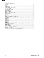
Page 2: ...nection and Installation 7 Binding a Receiver 7 Failsafe 8 Servo Reversing 8 Auxiliary Settings Linear 2 Position 3 Position 9 Travel Adjust 9 Steering Trim 10 Throttle Trim 10 Steering Rate 11 RF Mode 11 General Notes 11 Tips on Using 2 4GHz Systems 12 General Information 13 Warranty Information 13 Compliance Information for the European Union 16 Declaration of Conformity 16 Instructions for Disp...

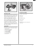
Page 3: ... that s immune to internal noisy motors ESCs etc and external interfering sources No longer will you have to wait for a frequency or worry about someone else being on the same channel With Spektrum when you re ready to race there s nothing stopping you Contents The DX3E radio system is supplied with the following DX3E transmitter SR300 receiver SPMSR300 1 S200 servo SPMS200 Bind plug SPM6802 4 AA ...

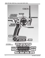
Page 4: ...ttle Reverse Travel Adjust Aux High Travel Adjust Aux Low Reverse Switch Throttle Reverse Switch Auxiliary Auxiliary Setting Switch tOP PANEL Antenna Steering Wheel Steering Rate Dial Steering Trim Dial Battery Indicator On Off Switch Aux Switch Bind Indicator Throttle Trim Dial Bind button Charge Jack on back Battery Door on bottom Reverse Switch Steering Throttle Trigger ...

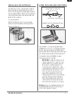
Page 5: ...sed they can be conveniently charged without removing them from the transmitter by using the charge jack located on the back side of the transmitters base Use Spektrum s charger SPM9526 to charge rechargeable batteries in the DX3E IMPORTANT All Spektrum charge jacks are center pin negative This is opposite of many chargers Before using a charger make sure the connector is center pin negative This ...

Page 6: ...ium or L large on the inside of the grip for easy identification To remove simply lift the edge of the grip and continue around the grip until it is completely removed To replace align the tabs of the grip to the slots in the handle and press the grip in place Receiver Compatibility The DX3E features DSM technology and is compatible with Spektrum DSM and DSM2 surface receivers and the marine recei...

Page 7: ...he red LED on the front of the transmitter will flash within a couple seconds indicating the transmitter is in bind mode Once the red LED begins flashing release the bind button Bind Plug LED 4 Within 15 seconds the LED on the receiver will go solid indicating a successful bind has taken place 5 Remove the bind plug and store it in a convenient place Note You must rebind when Different failsafe po...

Page 8: ...g the servos to their preset failsafe positions When the transmitter is turned on normal control is resumed Failsafe servo positions are set during binding see Bind on the previous page Servo Reversing Servo reversing is used to reverse the direction of the output of each channel e g a right steering command results in the wheels turning right To reverse a channel switch the position of the correl...

Page 9: ...lled proportionately Ideal for mixture control on engines Auxiliary Setting Switch Note that the servo reversing and travel adjust functions are used to adjust the endpoints and direction of the auxiliary channel TRAVEL ADJUST Travel adjust is used to limit the maximum travel that each channel will travel in each direction Travel adjust is independently adjustable in each direction To reduce the m...

Page 10: ...est position to be changed Normally steering trim is adjusted until the car tracks straight Steering Trim Dial THROTTLE Trim The throttle trim dial is used to adjust the throttle trim when the throttle stick is released neutral position This is typically used to adjust the brakes Rotating the dial causes the throttle trim the throttle position at rest to be changed Throttle Trim Dial EN ...

Page 11: ...ompetency must be high enough to ensure you are able to control your model under all conditions If you are a newcomer to radio controlled models please seek help from an experienced modeler or your local hobby shop Safety Points to Obey for Modelers Ensure your batteries both transmitter and receiver have been properly charged for your model Check all servos and their connections prior to each run...

Page 12: ...t all channels will be driven to the failsafe position set during binding When the transmitter is then turned on the transmitter scans the 2 4GHz band and acquires an open channel Then the receiver that was previously bound to the transmitter scans the band and finds the GUID Globally Unique Identifier code stored during binding The system then connects and operates normally If the transmitter is ...

Page 13: ...s warranty is limited to the original Purchaser Purchaser and is not transferable REPAIR OR REPLACEMENT AS PROVIDED UNDER THIS WARRANTY IS THE EXCLUSIVE REMEDY OF THE PURCHASER This warranty covers only those Products purchased from an authorized Horizon dealer Third party transactions are not covered by this warranty Proof of purchase is required for warranty claims Further Horizon reserves the r...

Page 14: ...be inspected or repaired please call for a Return Merchandise Authorization RMA Pack the Product securely using a shipping carton Please note that original boxes may be included but are not designed to withstand the rigors of shipping without additional protection Ship via a carrier that provides tracking and insurance for lost or damaged parcels as Horizon is not responsible for merchandise until...

Page 15: ... or repair should be shipped to the following address Horizon Hobby UK Units 1 4 Ployters Rd Staple Tye Harlow Essex CM18 7NS United Kingdom Please call 44 0 1279 641 097 or email us at sales horizonhobby co uk with any questions or concerns regarding this product or warranty Germany Electronics and engines requiring inspection or repair should be shipped to the following address Horizon Technisch...

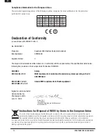
Page 16: ...nt Horizon Hobby Inc Instructions for Disposal of WEEE by Users in the European Union This product must not be disposed of with other waste Instead it is the user s responsibility to dispose of their waste equipment by handing it over to a designated collection point for the recycling of waste electrical and electronic equipment The separate collection and recycling of your waste equipment at the ...

Page 17: ... Horizon Hobby Inc The Spektrum trademark is used with permission of Bachmann Industries Inc Spektrum radios and accessories are exclusively available from Horizon Hobby Inc US Patent 7 391 320 Other patents pending www horizonhobby com www spektrumrc com Revised 10 2010 15697 5i ...

Reviews: