
3
Spektrum DX4r prO • tranSmitter inStructiOn manual
EN
TABlE OF CONTENTS
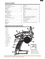
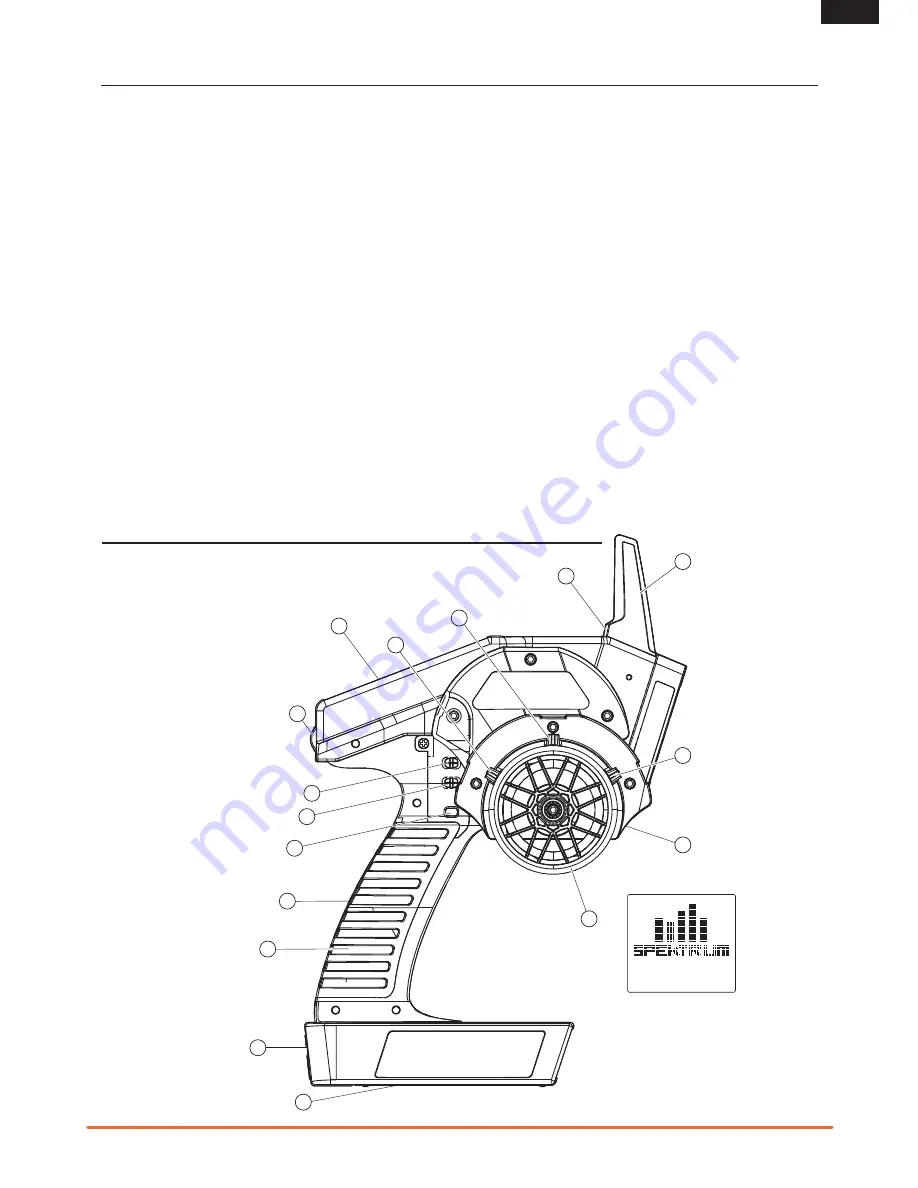
A. Switch A
B. Switch B
C. Switch C
D. Switch D
E. Switch E
F. Switch F
G. Roller Selector
H. Rubber Grip
I. Memory Card Port
(under rubber grip)
J. Power Switch
K. Battery Cover
L. Throttle Trigger
M. Steering Wheel
N. Antenna
O. LCD Screen
P. RF LED
IDENTIFyING CONTROlS AND SWITChES
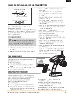
Slide the power switch (
J
)
to power ON the transmitter.
A Spektrum logo screen will
appear, then the Main Screen
will show on the LCD screen (
O
).
K
O
A
B
C
N
L
M
J
I
H
F
E
D
G
P
Warranty Registration ...................................................2
Identifying Controls and Switches ..................................3
Installing Batteries ........................................................4
ModelMatch ................................................................4
Charging .....................................................................5
The Rubber Grip ..........................................................5
Updating the Firmware .................................................5
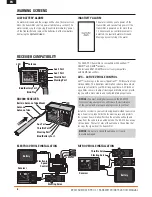
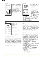
Warning Screens .........................................................6
Low Battery Alarm
Inactivity Alarm
Receiver Compatibility ..................................................6
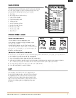
Main Screen ................................................................7
Programming Guide .....................................................7
Individual Direction Adjustments
List ............................................................................7
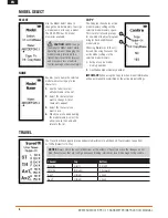
Model Select ...............................................................8
Travel ..........................................................................8
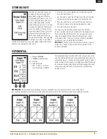
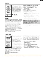
Steering Rate ...............................................................9
Exponential .................................................................9
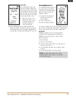
Binding......................................................................11
Frame Rate ................................................................11
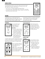
Servo Speed ..............................................................12
Mixing .......................................................................12
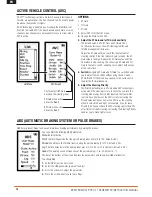
Active Vehicle Control (AVC) ........................................14
ABS (Automatic Breaking System or pulse brakes) .......14
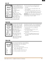
Idle Up ......................................................................15
Traction .....................................................................15
Trim Step ...................................................................15
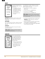
Reset ........................................................................16
Monitor .....................................................................16
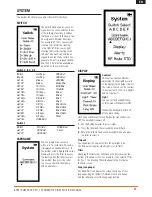
System .....................................................................17
Changing from Dropdown to Standard Wheel ..............19
Changing to Left-Handed Configuration .......................20
Troubleshooting Guide ................................................20
1-Year Limited Warranty .............................................21
FCC Information .........................................................22
IC Information ............................................................23
Compliance Information for the European Union ...........23


