background image

5

SPEKTRUM DX6 • TRANSMITTER INSTRUCTION MANUAL

EN

Battery and Charging Precautions and Warnings

Failure to exercise caution while using this product and comply with the following warnings could result in product malfunction, electrical 

issues, excessive heat, FIRE, and ultimately injury and property damage.

•  NEVER LEAVE THE BATTERY AND CHARGER UNATTENDED DURING USE
•  NEVER CHARGE BATTERIES OVERNIGHT

•  Read all safety precautions and literature prior to use of this product

•  Never

 allow minors to charge battery packs

•  Never

 drop charger or batteries

•  Never

 attempt to charge damaged batteries

•  Never

 attempt to charge a battery pack containing different types of batteries

•  Never

 charge a battery if the cable has been pinched or shorted

•  Never

 allow batteries or battery packs to come into contact with moisture at any time

•  Never

 charge batteries in extremely hot or cold places (recommended between 50–80˚ F or 10–27˚ C) or place in direct sunlight

•  Always

 disconnect the battery after charging, and let the charger cool between charges

•  Always

 inspect a new battery before charging

•  Always

 terminate all processes and contact Horizon Hobby if the product malfunctions

•  Always

 keep batteries and charger away from any material that could be affected by heat (such as ceramic and tile), as they can 

get hot

•  Always

 end the charging process if the charger or battery becomes hot to the touch or starts to change form (swell) during the 

charge process

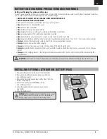
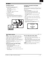
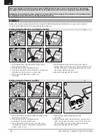
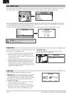
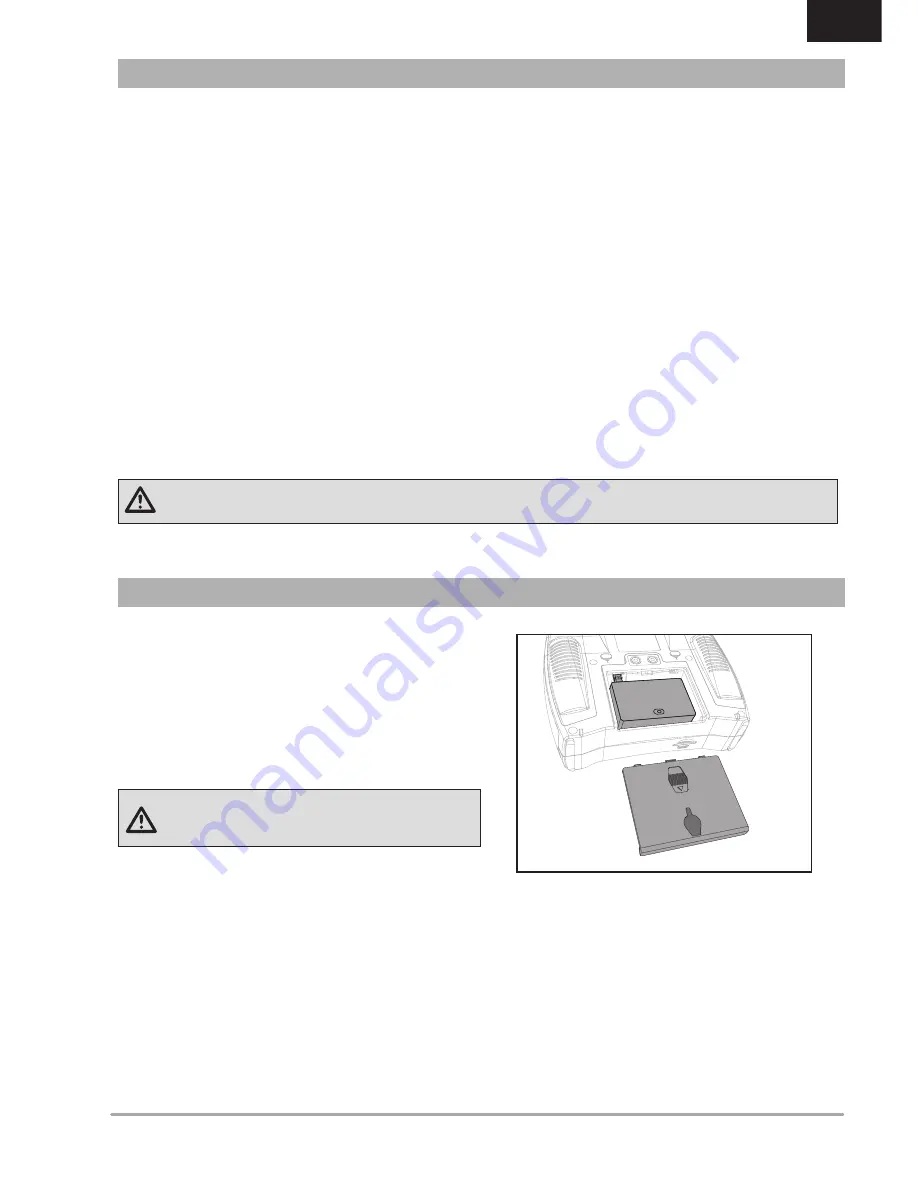
INSTALLING OPTIONAL LITHIUM ION BATTERY PACK

BATTERY AND CHARGING PRECAUTIONS AND WARNINGS

1. Remove battery cover from the back of the transmitter.
2. Remove the AA battery holder and disconnect from the 

transmitter power port.

3. Remove the Rectangle shaped foam and flat foam from the 

battery compartment.

4. Connect the battery pack (SPMA9602) to the  

transmitter power port.

5. Install the optional Lithium Ion battery pack into the  

transmitter.

6. Install the battery cover.

NOTICE:

 When installing a Lithium Ion battery pack, always 

set the battery chemistry to Lithium Ion in the Systems 

Setting screen to correctly set the low voltage alarm.

CAUTION

: Risk of explosion if battery is replaced by an incorrect type. Dispose of used batteries according to state and local laws.

Summary of Contents for DX6

Page 1: ...Instruction Manual Bedienungsanleitung Manuel d utilisation Manuale di Istruzioni Manual de instrucciones 6 6 ...

Page 2: ...dous when operated and maintained incorrectly Always install and operate a radio control system correctly Always pilot a model so the model is kept under control in all conditions Please seek help from an experienced pilot or your local hobby store Contact local or regional modeling organizations for guidance and instructions about flying in your area When working with a model always power on the ...

Page 3: ...r transmitter When you register your transmitter the reminder screen does not appear again BOX CONTENTS DX6 FEATURES Roll to telemetry screens without entering the Settings menu Switch between Function List and System Settings menus without powering off the transmitter Voice alerts for telemetry warnings and other conditions Selectable sound menu lets you activate or inhibit specific DX6 sounds As...

Page 4: ...Export Model 26 Update AirWare Software 27 Updating Spektrum DX6 Sound Files 27 Function List 28 Servo Setup 28 Travel Adjust 28 Sub Trim 28 Reverse 28 Differential ACRO and SAIL Types only 29 Throttle Cut ACRO and HELI Types only 29 Throttle Curve ACRO and HELI Types only 29 function list 29 D R Exponential 29 Mixing 30 Assigning a Mix to a Switch 30 Back Mixing 31 Range Test 31 Timer 31 Telemetr...

Page 5: ...harger cool between charges Always inspect a new battery before charging Always terminate all processes and contact Horizon Hobby if the product malfunctions Always keep batteries and charger away from any material that could be affected by heat such as ceramic and tile as they can get hot Always end the charging process if the charger or battery becomes hot to the touch or starts to change form s...

Page 6: ...Function 16 left Side Grip Neck Strap Mount 18 Rudder Trim Mode 1 2 Aileron Trim Mode 3 4 19 Elevator Trim Mode 1 3 Throttle Trim Mode 2 4 20 Elevator Rudder Stick Mode 1 Throttle Rudder Stick Mode 2 Elevator Aileron Stick Mode 3 Throttle Aileron Stick Mode 4 Function 21 Switch C 22 Switch B 23 Switch A 24 Switch D 25 Bind Switch I 26 LED The transmitter comes with a thin clear plastic film applie...

Page 7: ...djustment 4 Mode Change 5 Left Rear Grip Function 6 Audio Jack Charge Port For use with optional Lithium Ion Battery 8 Battery Cover 9 Trainer Port 10 Right Rear Grip Function 11 Gimbal Stick Tension Adjustment 12 Mode Change Throttle Spring Tension Adjustment Mode 1 3 TRANSMITTER FUNCTIONS F C D 6 6 8 9 10 12 1 13 4 11 7 2 3 5 3 13 7 ...

Page 8: ...ss Enter Choose or Exit Move between options or change value in an option Hold for 3 seconds and release to move to the Main Screen Turn Hold Press Tip The tick mark below shows the current switch position Rolling and clicking the scroll wheel turns the selected box black indicating that the value or condition will act on that position Function A Model Name DSMX DSM2 If not shown this indicates no...

Page 9: ...ml file on the card 7 Import My_DX6 xml into the Registration screen on the Spektrum Community site spektrumrc com SD CARD Update AirWare Software NOTICE The orange LED Spektrum bars flash and a status bar appears on the screen when AirWare software updates are installing Never power off the transmitter when updates are installing Doing so may damage the system files Before installing any AirWare ...

Page 10: ... receiver battery into ANY open port The receiver s LED will flash when the receiver is ready to bind 4 While pressing the Bind button power on the transmitter 5 Release the Bind button after the receiver has stopped flashing rapidly once the receiver s LED stays illuminated this indicates the receiver is bound to the transmitter The screen also provides binding information 6 Remove the bind plug ...

Page 11: ...he battery fully charges Ni MH batteries charged with peak detection fast chargers have a tendency to false peak i e not fully charge which could lead to a crash QuickConnect Technology with Brownout Detection DSM2 Only Your AR610 features QuickConnect technology with Brownout Detection Should an interruption of power occur brownout the system will reconnect immediately when power is restored The ...

Page 12: ...tle Hold Last Command The Hold Last Command failsafe maintains the last command on all channels except throttle If the radio signal is lost the aircraft maintains the commanded control inputs until the receiver regains signal To program Hold Last Command follow the provided binding instructions in this instruction manual To Test Hold Last Command 1 Power on the transmitter and receiver 2 Move one ...

Page 13: ...de Channel Assign Trim Setup Model Utilities Warnings Telemetry Preflight Setup Frame Rate Bind Trainer System Settings Transfer SD Card Function List Servo Setup D R and Expo Differential V Tail Differential Throttle Cut Motor Curve Camber Presets Camber System Mixing Range Test Timer Telemetry Custom Voice Setup System Setup Monitor ntial tup System Setup List Model Select Model Type Model Name ...

Page 14: ... List 3 Add a new model by rolling to the bottom of the list You will then be prompted with the Create New Model screen with the option to create a new model or cancel If you select Cancel the system will return to the Model Select function If you select Create the new model will be created and now be available in the model select list Direct Model Access Press the Clear and Back buttons from the ...

Page 15: ... 3P Switch 2 number of positions 2P 3P 2P 3P Flight Mode 1 Launch Launch Launch Launch Launch Launch 2 Cruise Cruise Cruise Cruise Cruise Cruise 3 Land Land Land 4 Thermal Thermal Thermal Thermal 5 Speed Speed Must be set up in a 4 5 flight mode SYSTEM SETUP Model Name Model Name enables you to assign a custom name to the current model memory Model names can include up to 20 characters including s...

Page 16: ...default then press the scroll wheel 3 Scroll left or right to view the options 4 Press the scroll wheel again to save the selection Channel Assignment The Channel Assignment function allows you to reassign almost any receiver channel to a different transmitter channel For example the receiver gear channel could be re assigned to the transmitter throttle channel 1 Scroll to the receiver channel you...

Page 17: ...ple the aircraft requires aileron trim in Flight Mode 1 but not in Flight Mode 2 Trim Assignment In a few instances you can reassign a trim to a different location Aircraft Model Type Throttle Throttle Digital trim button default Throttle Trim Type Common Flight Mode Trim Location Normal and Cross trim types are available Normal trims align with the control stick for example the throttle trim is n...

Page 18: ...to the desired model memory Press the scroll wheel once to save the selection 3 Select Copy and the Confirm Copy screen appears 4 Select Copy to confirm Selecting Cancel will return to the System Setup screen 5 Select the To model as the current model then bind the transmitter and receiver Copying a model does not copy the bind from the original model You cannot use the Model Copy screen to copy m...

Page 19: ... the main screen by pressing the scroll wheel Auto The Telemetry screen automatically appears as soon as the transmitter receives data from the telemetry module Units Scroll to Units and press the scroll wheel to change between US and Metric Telemetry Auto Configuration IMPORTANT The Auto Config option is not available from the System Setup Telemetry menu RF signal must be transmitting when you us...

Page 20: ...oss is not an error but there will be a momentary loss of radio signal when exiting the Telemetry screen DO NOT access the Telemetry menu during flight Preflight Setup The Preflight Setup menu option enables you to program a pre flight checklist that appears each time you power on the transmitter or when you select a new model memory Each item on the list must be confirmed before you can access th...

Page 21: ... slave transmitter It may be necessary for the slave transmitter to be in Inhibit mode to allow trim changes to transfer over from the master transmitter Slave Use Slave mode when using the DX6 as a slave transmitter and Pilot Link is active in the master transmitter DX6 Wired Trainer Operation 1 Bind the master transmitter to the model 2 Connect the trainer cord SPM6805 to the back of the master ...

Page 22: ...ter Pilot Link Master enables you to program the master transmitter to transfer any or all individual channels when you activate the trainer switch Pilot Link Master is ideal for complex models as the master transmitter maintains control of all secondary functions such as flight modes retracts flaps and brakes Secondary functions can be individually assigned to the Slave transmitter as necessary I...

Page 23: ...ustable in 10 increments from 10 darker to 100 brighter Mode You can change transmitter modes among Modes 1 2 3 and 4 This conversion requires both a programming and a mechanical change Please refer to Transmitter Mode Conversion for directions on making the necessary mechanical changes If mechanical changes are required for the mode you need to change to complete the mechanical changes first then...

Page 24: ...the current alarm time and press the scroll wheel 2 Scroll left or right to change the alarm time Press the scroll wheel to save the selection The Extra Settings screen enables you to Turn sounds off or on Change the appearance of the trim indicators Inh No alarm sounds 5 min 10 min Default 30 min 60 min System Sounds Scrolling to System Sounds and pressing the scroll wheel turns sounds on Active ...

Page 25: ...bal sticks to the center position 2 Select SAVE to store the calibration Serial Number Exporting the Serial Number to the SD Card You may find it helpful to export the transmitter serial number to a text file for your personal records or when you are registering the transmitter on the Spektrum Community To export the transmitter serial number 1 Insert an SD Card in the card slot on the transmitter...

Page 26: ... to 50 are the destination model number Your SD card can only contain 50 models Save files to folders on the card then remove from the card all unused models Files are selected by their position in the directory table Export Model You can use the Export Model option to export a single model file to the SD Card 1 Make sure the active model file is the one you wish to Export 2 Scroll to Select Optio...

Page 27: ...ate Update AirWare Software NOTICE The orange LED Spektrum bars flash and a status bar appears on the screen when AirWare software updates are installing Never power off the transmitter when updates are installing Doing so may damage the system files Before installing any AirWare files always Export All Models to an SD Card separate from the SD Card containing the update The update may erase all m...

Page 28: ...o save the selection Sub Trim Sub Trim adjusts the servo travel center point CAUTION Use only small sub trim values or you may cause damage to the servo Reverse Use the Reverse menu to reverse the channel direction For example if the elevator servo moves up and it should move down To reverse a channel direction 1 Scroll to Travel and press the scroll wheel Scroll left until Reverse appears and pre...

Page 29: ...croll wheel Scroll right to select On Differential is always on or assign the differential to a switch position 2 Press the scroll wheel a second time to save the selection 3 Scroll to the percentage selection and press the scroll wheel once to change the value 4 Press the scroll wheel again to save the selection Throttle Cut ACRO and HELI Types only The Throttle Cut menu option enables you to ass...

Page 30: ...odel memory Select a channel for master and slave Inputs for the master channel control both the master and slave channels For example Elevator to Flap makes elevator the master channel and flap the slave channel Offset Change the Offset value to move the effective center position of the slave channel Positive or negative value determines the direction of the offset Offset is not available for cur...

Page 31: ...the DX6 1 With the model restrained on the ground stand 30 paces approx 90 feet 28 meters away from the model 2 Face the model with the transmitter in your normal flying position and place the transmitter into Range Test mode see above Then push the trainer button the power output will be reduced 3 Operate the controls You should have total control of your model with the transmitter in Range Test ...

Page 32: ...t item on the list going through the list of user defined selections one by one Auto Cycle can be selected to Inhibit or Active If inhibited the system will go through the list 1 time only If the switch is triggered again when at the final item in the list it will not begin at the top of the list If Active the system will restart at the beginning of the list after the last item on the list with th...

Page 33: ...s NO to exit to the main screen and continue operation If you do not press YES or NO the system will exit to the main screen and continue operation within approximately 10 seconds WARNING Do not press YES unless the model is turned off or the model is secured Monitor The Monitor screen displays the servo positions for each channel graphically and numerically This is useful to verify programming fu...

Page 34: ...work correctly with your aircraft try V Tail B Wing Normal Flaperon Dual Aileron 1 Aileron 1 Flap 2 Ailerons 1 Flap Elevon A Elevon B Tail Normal V Tail A V Tail B Dual Elevator Dual Rudder A AUX1 servo port left aileron B AILE servo port right aileron C ELEV servo port left V tail D RUDD servo port right V tail E AILE servo port left aileron F ELEV servo port right aileron Recommended Servo Conne...

Page 35: ...list 3 Access the Function List from the Main Screen and select Flap System 4 Select Inhibit and scroll to the switch or lever you wish to use to control the flap channel 5 Assign the Flap travel values and any desired Elevator mixing 6 Select a Flap speed if desired Norm default does not have a delay Flap speed options range from 0 1s to 30 seconds ACRO Mixing Rudder to Aileron Elevator Rudder to...

Page 36: ...ows the throttle pitch stick to operate in reverse and ensures trims curves and all other functions that are to work in reverse function properly Pitch Curve This function supports adjustment of collective pitch in 5 flight modes To adjust the Pitch Curve 1 Select the Pitch Curve you wish to edit N 1 or 2 2 Scroll right to select the points on the curve and edit the respective values 3 Press the B...

Page 37: ...yro menu option enables you to assign a gyro gain value to an independent switch or a Flight Mode Assign the receiver channel connected to the gyro then assign the switch for gyro options You can also assign values to available switch positions from 1 to 4 rates are available depending on the switch assigned Make sure the gyro operates correctly and compensates in the correct direction Mixing Cycl...

Page 38: ...re not active only one preset position is available and it is always active The Camber Preset Speed enables the control surfaces to transition over a period of time up to 30 seconds when you change flight modes Move the flight mode switch to the desired position to change the Camber Preset values Wing 1 Servo 2 Aileron 2 Aileron 1 Flap 2 Aileron 2 Flap Tail Normal V Tail A V Tail B Motor Inhibit A...

Page 39: ...Camber System The Flap to Elevator mix operates as a curve so that the elevator moves down the most during the first 20 of flap deployment decreases over the next 40 then remains the same from 60 to 100 of flap travel For sailplanes with ailerons tips flaps make sure an appropriate Sailplane Type is selected so that tips appear in the transmitter as RAIL and LAIL Decrease or increase travel on the...

Page 40: ... Friction Straps section Transmitter Mode Conversion You can change transmitter modes among Modes 1 2 3 and 4 This conversion requires both a programming and a mechanical change Programming Conversion 1 Access the System Settings menu from the Setup List and select the desired Mode If you are changing between Modes 2 4 or 1 3 you can STOP after Step 1 2 Exit the System Settings menu to save the se...

Page 41: ...justing the elevator centering screw Holding the gimbal stick reduces the load on the elevator centering mechanism and makes it easier to adjust the centering screw 2 Locate the gimbal where the elevator centering spring is engaged Use a Phillips screwdriver to tighten the elevator centering screw Tightening the screw will disengage the centering spring 3 Using a Phillips screwdriver loosen the op...

Page 42: ... transmitter to adjust the stick gimbal tension Only the top of the grip must be pulled up to access the adjustment screw The entire grip does not need to be removed 2 Turn the screws in these holes marked with a vertical or horizontal arrow a small amount using a small Phillips screwdriver NOTICE Always do a test of stick tension while turning these screws to ensure stick tension is not too loose...

Page 43: ...eceiver or receiver extension Required remote receiver is not connected The receiver goes into failsafe mode a short distance away from the transmitter Check the receiver antenna to be sure it is not cut or damaged Replace or contact Horizon Product Support Main and remote receivers too near each other Install main and remote receivers at least 2 inches 51mm apart Receiver quits responding during ...

Page 44: ...event that you may need any assistance For questions or assistance please visit our website at www horizonhobby com submit a Product Support Inquiry or call the toll free telephone number referenced in the Warranty and Service Contact Information section to speak with a Product Support representative Inspection or Services If this Product needs to be inspected or serviced and is compliant in the c...

Page 45: ...ww modelaircraft org The Federal Aviation Administration can be found online at www faa gov Country of Purchase Horizon Hobby Contact Information Address United States of America Horizon Service Center Repairs and Repair Re quests servicecenter horizonhobby com RequestForm 4105 Fieldstone Rd Champaign Illinois 61822 USA Horizon Product Support Product Technical As sistance www quickbase com db bgh...

Page 46: ...2014 Instructions for disposal of WEEE by users in the European Union This product must not be disposed of with other waste Instead it is the user s responsibility to dispose of their waste equipment by handing it over to a designated collections point for the recycling of waste electrical and electronic equipment The separate collection and recy cling of your waste equipment at the time of dispos...

Reviews: