background image

53706
© 2016 Horizon Hobby, LLC.
DSM, DSM2, DSMR and RaceWare are trademarks or registered trademarks of Horizon Hobby, LLC. 
The Spektrum trademark is used with permission of Bachmann Industries, Inc.
Android is a trademark of Google Inc. The Bluetooth

®

 word mark and logos are registered trademarks owned 

by Bluetooth SIG, Inc. and any use of such marks by Horizon Hobby is under license.  
The WiFi logo is a registered trademark of WiFi Alliance. The SD Logo is a trademark of SD-3C, LLC.
All other trademarks, service marks and logos are property of their respective owners.  
US 9,320,977. Other patents pending.
08/16 


Summary of Contents for DX6R

Page 1: ...DX6R DX6R 6 Channel 2 4GHz DSMR System 6 Channel 2 4GHz DSMR System Instruction Manual Bedienungsanleitung Manuel d utilisation Manuale di istruzioni ...

Page 2: ...of physical property damage AND a possibility of serious injury WARNING Procedures which if not properly followed create the probability of property damage collateral damage and serious injury OR create a high probability of superficial injury WARNING Read the ENTIRE instruction manual to become familiar with the features of the product before operating Failure to operate the product correctly can...

Page 3: ...ing or swelling can result in fire Always store the battery at room temperature in a dry area for best results Always transport or temporarily store the battery in a temperature range of 40 120º F 5 49 C Do not store the battery or model in a car or direct sunlight If stored in a hot car the battery can be damaged or even catch fire Always charge batteries away from flammable materials Always insp...

Page 4: ...teering Travel 19 Steering Subtrim 19 Reverse 19 Throttle Brake Reverse 20 Throttle Curve 20 Brake Curve 21 Throttle Trim 21 Throttle Rate 21 Reverse Rate 22 Brake Rate 22 Traction control 22 ABS Automatic Braking System 22 Idle Up 22 AWD Mode MOA 23 Servo Speed 23 Channel properties 23 Travel 23 Throttle Subtrim 23 Reverse 23 Auxiliary aux channel setup 24 Input Control 24 AUX Curve 24 Servo Spee...

Page 5: ...et Spacer set Steering Wheel set Power Supply Sticker set Support Videos For helpful videos on programing the Spektrum DX6R and other Spektrum Transmitters go to https www spektrumrc com The DX6R features a Micro SD card reader card not included and a Micro USB port enabling you to update the transmitter when firmware and Raceware updates are available Register your transmitter at www SpektrumRC c...

Page 6: ...harging base 4 The LED will blink blue to indicate the battery is charging The LED will turn off when the unit goes to sleep 5 Disconnect the transmitter from the charging base once charging is complete and disconnect the power supply from the power outlet CAUTION Never leave a charging battery unattended CAUTION Never change the low voltage limit for Li Ion batteries below 3 3V Doing so could ove...

Page 7: ...ton G Power LED H Memory Card USB Port I Switch I J Knob K Head Phone Jack L Button B Function M Button F N Button G O Button H P Trigger throttle brake Q Button A R Button E S Button D T Button C U Speaker V Antenna W Charge Base Transmitter Functions I J K L M N O P Q R S T U V A B C D E F G H W ...

Page 8: ...l 8 16 8 16 8 16 AIRW AR E AIRW AR E DX 6R Ma nu al DX 6R Ma nu al Home Screen 1 App Drawer Contains applications loaded onto the DX6R 2 Back Return to previous screen 3 Home Return to the home screen 4 Overview Allows switching between any of the running applications 75 08 16 Monday 23 May NOTIFICATIONS Wi Fi Bluetooth RACEWARE RACEWARE DX6R Manual DX6R Manual RACEWARE RACEWARE DX6R Manual DX6R M...

Page 9: ...creen From the Notification screen you can quickly edit these settings ANDROID operating system 75 08 16 Monday 23 May NOTIFICATIONS Wi Fi Bluetooth RACEWARE RACEWARE DX6R Manual DX6R Manual RACEWARE RACEWARE DX6R Manual DX6R Manual 2 1 3 4 5 6 8 16 8 16 8 16 AIRW AR E AIRW AR E DX 6R Ma nu al DX 6R Ma nu al For more information on using the Android OS tap on the Quick Start Guide icon below Tip ...

Page 10: ...to create your first model See the Model Setup section for more information Raceware operation 08 16 Monday 23 May NOTIFICATIONS Wi Fi RACEWARE RACEWARE DX6R Manual DX6R Manual RACEWARE RACEWARE DX6R Manual DX6R Manual To navigate around the DX6R use your finger to tap swipe and drag icons and menus found on the display 8 16 8 16 8 16 AIRW AR E AIRW AR E DX 6R Ma nu al DX 6R Ma nu al 8 16 8 16 8 1...

Page 11: ...the name field to access the keypad Enter a user name using up to 20 characters After initial setup the name can be changed in the App Set tings screen Model Name Tap in the name field to access the keypad Enter a model name using up to 20 characters Receiver type Select from a list of compatible Spektrum DSMR Receivers AVC TECHNOLOGY Activates or deactivates AVC technology in this model This menu...

Page 12: ...r or servo If there are open AUX channels select the AUX channel and create a name for the function being used e g Winch RX output map Once all options are made the RX Output Map will outline the current receiver connections Double check that all options have an assigned channel Binding When the model is complete the last option is to bind your model to the transmitter See BINDING section for more...

Page 13: ...ric Reverse Gas Nitro AVC ON 2CH 3CH 6CH Receiver 4CH Single MOA Power System Power System YES NO Reverse Motors Throttle Brake YES NO 1CH 2CH Single Dual Independant Channels Front Rear Motors Only on first activation Steering AUX 1 AUX 2 AUX 1 AUX 1 Model Setup ...

Page 14: ... only available if you are using a telemetry capable receiver MONITOR Monitor can be found by swiping right from the Dashboard or Telemetry screens if available The Monitor displays the position of the Steering Wheel Throttle Brake Trims and the position of any AUX channels SETUP Setup can be found by swiping right from the Monitor screen Setup is where the majority of model setup takes place The ...

Page 15: ...el list Tap on the down arrow to move a model down the list Tap on the up arrow to move up on the list Import Model Tap Import from SD to import from SD card Tap Receive via Bluetooth to import over Bluetooth The Model screen is accessed by tapping the model image in the top right corner of every main screen Use the Models Screen to Create New Models Import Models Activate Models in List Sort Mode...

Page 16: ...0 characters Theme color Tap the color box to select a different theme color Model Image Tap the PHOTO box to change the image Use the PHOTO PICKER to select an image from an SD card Export Model Tap EXPORT to SD to export current model to SD card Tap transfer via bluetooth to export a model directly to another transmitter Duplicate delete Model Tap DUPLICATE THIS MODEL to make a copy of the curre...

Page 17: ...ing Curve Steering response is adjustable using an EXPO or Custom steering curves The STEERING screen allows for programming of all steering functions Available functions Steering Curve Steering Trim Steering Speed Steering Rate Channel Properties AWS Mode Travel Subtrim Reverse Standard Linear steering output default Exponential Positive EXPO values decrease steering sensitivity around neutral St...

Page 18: ...low Delete a point by tapping on it then select Delete point red box above graph Look for the On the Fly Button in most menus Allows for on the fly adjustments of menu items Tip Steering Trim Steering trim adjusts the steering neutral position Steering Trim is defaulted to Switch B but can be assigned to any trimmer switch Common Drive Mode Steering speed Reduces servo output transit time slows do...

Page 19: ...wheel steering Front Wheel Steering Rear Wheel Steering 4 Wheel Steering 4 Wheel Crab Steering Drive Modes must be select when AWS is active Steering Travel Allows independent adjustments of the right and left steering end points Adjustment range is 0 to 150 Reverse Reverses servo output direction Steering Subtrim Used to correct minor servo arms linkages inaccuracy s important Use minimal Subtrim...

Page 20: ...el Properties Travel Subtrim Reverse Standard Linear throttle output default Exponential Positive EXPO values decrease throttle sensitivity around neutral Custom Up to 7 selected points can be adjusted to custom tailor throttle response throughout the range Tap on the line to add points Tap on a point to adjust its position using the sliders below Delete a point by tapping on it then select Delete...

Page 21: ...sing the sliders below Delete a point by tapping on it then select Delete point red box above graph On the Fly Button Select a switch for instant adjustment of the expo curve while driving Throttle Brake Reverse Throttle Trim Throttle trim adjusts the steering neutral position and is used to adjust static brakes Throttle Trim is defaulted to Switch A but can be assigned to any trimmer switch Commo...

Page 22: ...tput is above that point Traction control can be assigned to any trimmer switch ABS Automatic Braking System ABS helps prevent brake lock ups and improves braking performance by pulsing the brakes Engagement Point The throttle position that the pulse braking takes place 0 to 100 default is 60 Pulse Width The distance the throttle travels during the pulse braking 0 to 100 default is 50 Pulse Per Se...

Page 23: ...ssigned to a trimmer Switch Servo Speed Reduces servo output transit time slows down the servo Servo Speed can be assigned to any trimmer switch Channel properties Displays current position of the steering wheel Travel Allows independent precise adjustments of the brake end points Reverse Reverses servo output direction Throttle Subtrim Used to correct minor servo arms linkages inaccuracy s import...

Page 24: ... channel functions Available functions Input Control Aux Curve Aux Speed Channel Properties Travel Subtrim Reverse Standard Linear output default Exponential Positive EXPO values decrease sensitivity around neutral Custom Up to 7 selected points can be adjusted to custom tailor AUX channel response throughout the range Tap on the line to add points Tap on a point to adjust its position using the s...

Page 25: ...annel properties Displays current position of the AUX channel Travel Allows independent precise adjustments of the end points Reverse Reverses servo output direction Throttle Subtrim Used to correct minor servo arms linkages inaccuracy s important Use minimal Subtrim values Subtrim offsets the entire stroke including the center and endpoint positions ...

Page 26: ...ogy is available only when an AVC capable receiver is selected Enable Disable Turn AVC on or off Steering Gain The default value is 50 As the value increases the AVC steering stability increases If the front wheels begin to shake the ST Gain value is too high Reduce the ST Gain value until the front wheels stop shaking Throttle Gain The default value is 50 As the value increases the throttle manag...

Page 27: ...rate other than 5 5ms is selected the Aux channels will operate as extra servo channels 2 With the receiver in bind mode Tap the Begin Binding button important Re bind any time you change the frame rate in the transmitter avc Active Vehicle Control Priority The default value is 0 meaning AVC technology is active throughout the steering range As you turn the steering wheel away from center neutral ...

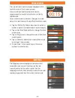
Page 28: ...tton or switch to enable instant mode changes Tap on the Drive Mode button to change the drive mode name Tap on Flag Color to change the color of the Drive mode banner Tap on Delete to delete drive modes there must be at least 1 drive mode If more than 1 drive mode tap on the arrow buttons to order the list The Mapping screen displays an overview of all transmitter and receiver functions as they a...

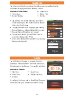
Page 29: ...hold per sensor Choose motor sensor type and Pole Count to accurately display motor RPM s Select drive ratios and tire diameter to accurately display model speeds Available functions Temperature Receiver Battery Speed RPM Sensor Type Roll Out Available Timers Total Time Model Time Up Timer Down Timer Rolling Lap Timer The DX6R offers 5 timers all viewable from the Dashboard Pause and Reset the tim...

Page 30: ...a a selectable button switch When the down timer expires an Alert will sounds and the timer begins to count up Select minutes 0 599 and seconds 0 59 by tapping in the appropriate box Select the button or switch to activate pause and reset the timer This timer can also be paused or reset on the main DashBoard screen Rolling Lap Timer Start the Rolling Lap Timer via a selectable programmable switch ...

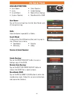
Page 31: ...etric Version Serial Number Scroll Wheel Configure the Scroll Wheels button push to jump to one of these four screens Create Backup Tap on the Create Backup button to save a backup copy of the DX6R Restore from Backup Tap on the Restore from Backup button to restore the DX6R from a saved version Recalibrate DX6R Tap on the Recalibrate dx6r button to enter into recalibration mode Follow the on scre...

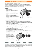
Page 32: ...sion Available adjustments Adjustable trigger and steering tension Multiple trigger position Multiple wheel drop down options 10 and 15 Steering Adapters Small and Large Steering Wheel Left or right hand steering 3 grip sizes Throttle Distance Angle 2 5mm hex wrench loosen 1 to 2 turns Adjust IN or OUT Tighten Throttle Tension 1 5mm hex wrench Clockwise to decrease tension Steering Tension 1 5mm h...

Page 33: ...arefully disconnect the 2 wiring harness from inside the transmitter Using a 1 5mm hex wrench remove the steering wheel Using a 2mm hex wrench remove 2 screws from the steering mechanism Remove the steering mechanism from the drop down being careful to pull the wiring harness through the opening Keep the drop down in a safe place for future use Connect the 2 wiring harnesses to the board inside th...

Page 34: ...at the factory Lift the edge of the grip and pull the grip away from the handle Align the tabs on the new grip with the slots in the handle Press the grip against the handle Refer to the Dropdown steering wheel options section for directions on removing and installing the steering mechanism Choose the 10º or 15º wedge The wedge goes between the steering mechanism and the drop down or transmitter i...

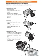
Page 35: ...ve the 2 wire connectors from the board inside the transmitter Set aside Back Cover Using a 2mm hex wrench remove 2 screws Remove the back cover and re install on the opposite side of the transmitter Steering mechanism Connect the 2 wire connectors to the board inside the DX6R Note that one connector has 6 pins and the other has 7 Align with screw holes and re install the 3 screws being careful no...

Page 36: ...wiring harness from the board inside the transmitter Installing the assemblies Install the assemblies on the opposite face of the transmitter Connect the wiring harness to the board inside the DX6R Carefully seat the assemblies into face of the transmitter being careful not to pinch any wires Install the one Phillips head screw into each assembly Wiring not shown IMPORTANT There is a 4 pin and 5 p...

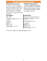
Page 37: ...els 2 Weight 5 5 g Band 2 4GHz Voltage Range 3 5 9 6V SR6000T Telemetry Receiver The Spektrum SR6000T Telemetry Re ceiver is compatible with all Spektrum DSMR surface transmitters Telemetry functions require a Spektrum transmi tter capable of telemetry Specifications Type DSMR with internal telemetry Dimensions LxWxH 37 5 x 27 7 x 15 7mm Antenna Length 210mm Channels 6 Weight 9 2 g Band 2 4GHz Vol...

Page 38: ...Horizon has no control over use setup final assembly modification or misuse no liability shall be assumed nor accepted for any resulting damage or injury By the act of use setup or assembly the user accepts all resulting liability If you as the purchaser or user are not prepared to accept the liability associated with the use of the Product purchaser is advised to return the Product immediately in...

Page 39: ...lled for return freight Horizon accepts money orders and cashier s checks as well as Visa MasterCard American Express and Discover cards By submitting any item to Horizon for service you are agreeing to Horizon s Terms and Conditions found on our website http www horizonhobby com content service center_ render service center ATTENTION Horizon service is limited to Product compliant in the country ...

Page 40: ...tion between the equipment and receiver Connect the equipment to an outlet on a circuit different from that to which the receiver is connected This device complies with part 15 of the FCC rules Operation is subject to the following two conditions 1 This device may not cause harmful interference and 2 this device must accept any interference received including interference that may cause undesired ...

Page 41: ...s responsibility to dispose of their waste equipment by handing it over to a designated collection point for the recycling of waste electrical and electronic equipment The separate collection and recycling of your waste equipment at the time of disposal will help to conserve natural resources and ensure that it is recycled in a manner that protects human health and the environment For more informa...

Page 42: ... is a trademark of Google Inc The Bluetooth word mark and logos are registered trademarks owned by Bluetooth SIG Inc and any use of such marks by Horizon Hobby is under license The WiFi logo is a registered trademark of WiFi Alliance The SD Logo is a trademark of SD 3C LLC All other trademarks service marks and logos are property of their respective owners US 9 320 977 Other patents pending 08 16 ...

Reviews: