background image

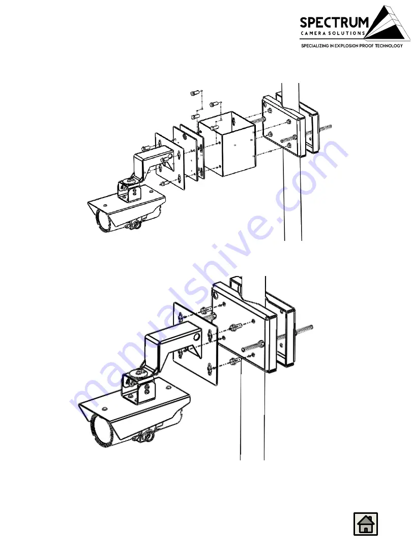
F1XX-WM+SD-PMA

ASSEMBLY MOUNTS

F1XX-WM+SD-VM+SD-SO+ SD-PMA

F101-P137(5,7,8)-BD REV 2 114309212018 F1XX 

SERIES INSTALLATION REV-2A

28

Summary of Contents for F101-P137-BD Series

Page 1: ...SPECTRUM F101 P137X BDSeries F101 P1375 BD F101 P1377 BD F101 P1378 BD Explosion Proof NetworkCamera Installation Manual F101 P137 5 7 8 BDREV 2 114309212018F1XX SERIES INSTALLATION REV 2A 1 ...

Page 2: ...ll trademark s and the rights of the trademark s owned by the company referred to herein Release Date 02 05 2020 Document Name F101 P137 5 7 8 BD INSTALLATIONMANUAL Copyright 2020 by Spectrum Camera Solutions LLC All rightsreserved RevisionRecord Rev Description Date 0 Initial Release 02 05 2020 1 coc 02 18 2020 2 Update Parameters 5 14 2020 F101 P137 5 7 8 BDREV 2 114309212018F1XX SERIES INSTALLA...

Page 3: ... 4 LABELS 5 STANDARDS AND CERTIFICATIONS 6 DOCUMENT SYMBOLS 7 HOW TO USE THIS MANUAL 8 GENERAL SAFETY AND OPERATING INFORMATION 9 SPECIFICATIONS 12 UNBOXING HARDWARE 14 WIRING ENTRIES 16 INSTALLATION 17 DISMANTLING AND MAINTENANCE 21 F101 P137 5 7 8 BDREV 2 114309212018F1XX SERIES INSTALLATION REV 2A 3 ...

Page 4: ...tions involved Disclaimer Spectrum Camera Solutions LLC makes no representations or warranties with respect to the contents hereof Further Spectrum Camera Solutions LLC reserves the right to revise this publication and to make changes in the content hereof without obligation to notify any person or organization of such revision or changes Trademark Information Spectrum Camera Solutions LLC and its...

Page 5: ...Labels F101 P137 5 7 8 BDREV 2 114309212018F1XX SERIES INSTALLATION REV 2A 5 ...

Page 6: ...ints is necessary Follow the manufacturer s instructions to reduce the potential of an electrostatic charging hazard on the surface of the equipment in Group II and III environments NOTE Use a clean cloth dampened with pure water forcleaning CERTIFICATIONS CERT NO FM18US0262X FM18CA0126X US Class I Division 1 Groups BCD T5 Ta 40 C to 55 C Type 4X IP66 Class II III Division 1 Groups EFG Ta 40 C to ...

Page 7: ...of electric shock or high temperature parts may result in injury if proper precautions are not taken NOTE Emphasizes important or essential information Locating Information NOTE In the interest of completeness manuals and drawings included with the system may provide information pertaining to options not included with your equipment Information in application notes supersedes general information i...

Page 8: ...nual are not designed to replace or supersede required or common sense safety practices All safety warnings listed in any documents applicable to equipment and parts used in or with the system described in this manual must be read and heeded before commencing work on any part of the system NOTE Refer to all ATEX CSA IECEx NEC NFPA EAC Ex and FM certificates for any Special Conditions of Use If the...

Page 9: ...cation s if unauthorized repairoccurs General Precautions Slip resistant gloves and protective eyewear glasses with side shields or goggles as appropriate should be worn when installing and servicing any part of electrical equipment Hot components should be allowed to cool before servicing if possible Other appropriate equipment or clothing must be used as required by the type of work performed Al...

Page 10: ...ting structure CAUTION The electrical cover should never be removed unless power is removed for at least 5 minutes from the unit or the area is known not to contain hazardousgases NOTE The product shall be installed by a trained professional The product shall be used in compliance with local laws and regulations Store the product in a dry and ventilatedenvironment Avoid exposing the product to sho...

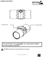
Page 11: ...al housing compartment The connection to the external circuits must be realized by cable glands or pipe fittings covered by a separate certificate s If a cable gland is not used or an entry is open the entry must be closed by a stopping plug covered by a separate certificate The thread diameter of the cable entry is inch NPT This equipment can be used with different voltage and power the nominal p...

Page 12: ... Type 4X IP66 II 2 G Ex db IIB H2 T5 Gb Ta 50 C to 55 C IP66 II 2 D Ex tb IIIC T85 C Db Ta 50 C to 55 C IP66 CERT NO FM18ATEX0073X IECEx FMG 18 0029X CERT NO RU 0690907 1Ex d IIВ Н2 T5 Gb X Ta 50 C to 55 C IP66 Ех tb IIIС T85 ºС Db Х Ta 50 C to 55 C IP66 ELECTRICAL REQUIREMENTS of Model F101 P1377 BD POWER INPUT CONSUMPTION Camera IEEE 802 3af 802 3at Type 1 Class 3 10 7W Heating 12 24vdc vac 25W ...

Page 13: ...2 2 of IEC EN UL 60950 1 and Limited Power Source LPS according to clause 2 5 of IEC EN UL 60950 1 or CEC NEC Class 2 source of supply as defined in the Canadian Electrical Code CSA C22 1 and National Electrical Code ANSI NFPA 70 Class 1 electrical energy source ES1 and Class 2 power source PS2 rated output power limited to 100 W according to IEC EN UL 62368 1 When used with Power over Ethernet Po...

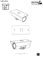
Page 14: ...UNBOXING F101 P137 5 7 8 BDREV 2 114309212018F1XX SERIES INSTALLATION REV 2A 14 ...

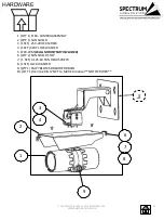
Page 15: ...R 5 F1XX WM WALL MOUNT NOT INCLUDED 6 QTY 2 SUN SHIELDSTOP 7 1 SET 3125 18 PAN HEAD SCREW 8 1 SET LOCK WASHER 9 QTY 1 CMP 781DT25 BREATHER DRAIN 10 QTY 1 R1 3 4 20 N NPT to M20 EX reducer NOTPICTURED 1 5 8 6 7 3 4 2 9 HARDWARE F101 P137 5 7 8 BDREV 2 114309212018F1XX SERIES INSTALLATION REV 2A 15 ...

Page 16: ...duit Entries are inch NPT Use appropriate adapter to keep ingress protection CAUTION Ensure power is disconnected prior to connecting NPTPORT NPTPORT F101 P137 5 7 8 BDREV 2 114309212018F1XX SERIES INSTALLATION REV 2A 16 ...

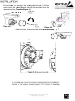
Page 17: ...g and remove 20 hex screws from the sunshield and then lift the sunshield from the camera housing Tabletop Figure 2 1 20 hex screws Figure 2 2 Set screw If wall mounted remove sunshield stop F101 P137 5 7 8 BDREV 2 114309212018F1XX SERIES INSTALLATION REV 2A 17 ...

Page 18: ...on terminal block and insert positive 12 24 VDC VAC connection into terminal block A release to secure Do the same for negative dc connection into terminal block B B A F101 P137 5 7 8 BDREV 2 114309212018F1XX SERIES INSTALLATION REV 2A 18 ...

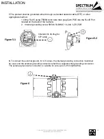
Page 19: ...l grounding screw 5850 6 SLBHUC 10 24x ZS ZGR Figure 5 1 Shielded RJ 45 Plugfor STP cable Figure 5 2 6 To connect the external ground for U S zones the internal grounding connection must shall be used and the external grounding connection shall be a supplemental grounding connection The external ground wire connection is suitable for wire up to 3 25 mm 8AWG Figure6 F101 P137 5 7 8 BDREV 2 11430921...

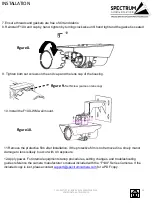
Page 20: ... wall mount 11 Remove the protective film after installation If the protective film is not removed in a timely manor damage to lens is likely to occur with UV exposure 12 Apply power For internal equipment startup procedures setting changes and troubleshooting guides reference the camera manufacturer s manual included with the F1XX Series Cameras If the included copy is lost please contact support...

Page 21: ...ce cleaner Never use harsh chemicals or abrasive towels Replacing the battery The F101 P137 5 7 8 BD product uses Maxell 3 0 V CR2032 lithium battery Lithium primary battery composed of cathode from Manganese Dioxide Organic electrolyte Lithium as the power supply for its internal real time clock RTC Under normal conditions this battery will last for a minimum of five years Low battery power affec...

Page 22: ...37 5 7 8 BDREV 2 114309212018F1XX SERIES INSTALLATION REV 2A 22 Spectrum Camera Solutions declares that under our sole responsibility thatthe product s listed below conform to the relevant provisions of 2014 34 EU of November 08 2018 Doc No F1xx 10107152019 2014 34 EU ...

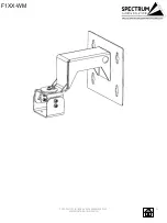
Page 23: ...F1XX WM F101 P137 5 7 8 BDREV 2 114309212018F1XX SERIES INSTALLATION REV 2A 23 ...

Page 24: ...SD PMA POLE MOUNTADAPTER HARDWARE QTY 4 M10 1 75 18 8 Bolts QTY 2 12in all thread with nuts and washers QTY 2 A1612 sides F101 P137 5 7 8 BDREV 2 114309212018F1XX SERIES INSTALLATION REV 2A 24 ...

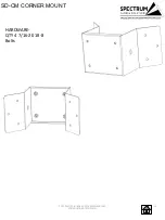
Page 25: ...SD CM CORNER MOUNT HARDWARE QTY 4 7 16 20 18 8 Bolts F101 P137 5 7 8 BDREV 2 114309212018F1XX SERIES INSTALLATION REV 2A 25 ...

Page 26: ...SD VM VIBRATION MOUNT HARDWARE QTY 4 7 16 20 18 8 Bolts FRONT F101 P137 5 7 8 BDREV 2 114309212018F1XX SERIES INSTALLATION REV 2A 26 ...

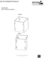
Page 27: ...SD SO STANDOFF MOUNT HARDWARE QTY 4 7 16 20 18 8 Bolts FRONT BACK F101 P137 5 7 8 BDREV 2 114309212018F1XX SERIES INSTALLATION REV 2A 27 ...

Page 28: ...F1XX WM SD PMA ASSEMBLY MOUNTS F1XX WM SD VM SD SO SD PMA F101 P137 5 7 8 BDREV 2 114309212018F1XX SERIES INSTALLATION REV 2A 28 ...

Reviews: