


76
M3i.48xx / M3i.48xx-exp Manual
Buffer handling
Acquisition modes
Directly after start of transfer the SPC_DATA_AVAIL_USER_LEN is every time zero as no data is available for the user and the
SPC_DATA_AVAIL_CARD_LEN is every time identical to the length of the defined buffer as the complete buffer is available for the card for
transfer.
The counter that is holding the user buffer available bytes (SPC_DATA_AVAIL_USER_LEN) is sticking to the de-
fined notify size at the DefTransfer call. Even when less bytes already have been transferred you won’t get
notice of it if the notify size is programmed to a higher value.
Remarks
• The transfer between hardware FIFO buffer and application buffer is done with scatter-gather DMA using a busmaster DMA controller
located on the card. Even if the PC is busy with other jobs data is still transferred until the application data buffer is completely used.
• Even if application data buffer is completely used there’s still the hardware FIFO buffer that can hold data until the complete on-board
memory is used. Therefore a larger on-board memory will make the transfer more reliable against any PC dead times.
• As you see in the above picture data is directly transferred between application data buffer and on-board memory. Therefore it is abso-
lutely critical to delete the application data buffer without stopping any DMA transfers that are running actually. It is also absolutely criti-
cal to define the application data buffer with an unmatching length as DMA can than try to access memory outside the application data
area.
• As shown in the drawing above the DMA control will announce new data to the application by sending an event. Waiting for an event is
done internally inside the driver if the application calls one of the wait functions. Waiting for an event does not consume any CPU time
and is therefore highly desirable if other threads do a lot of calculation work. However it is not necessary to use the wait functions and
one can simply request the current status whenever the program has time to do so. When using this polling mode the announced avail-
able bytes still stick to the defined notify size!
• If the on-board FIFO buffer has an overrun (card to PC) or an underrun (PC to card) data transfer is stopped. However in case of transfer
from card to PC there is still a lot of data in the on-board memory. Therefore the data transfer will continue until all data has been trans-
ferred although the status information already shows an overrun.
• Getting best bus transfer performance is done using a „continuous buffer“. This mode is explained in the appendix in greater detail.
The Notify size sticks to the page size which is defined by the PC hardware and the operating system. There-
fore the notify size must be a multiple of 4 kByte. For data transfer it may also be a fraction of 4k in the
range of 16, 32, 64, 128, 256, 512, 1k or 2k. No other values are allowed. For ABA and timestamp the notify
size can be 2k as a minimum. If you need to work with ABA or timestamp data in smaller chunks please use the
polling mode as described later.
The following graphs will show the current buffer positions in different states of the transfer. The drawings have been made for the transfer
from card to PC. However all the block handling is similar for the opposite direction, just the empty and the filled parts of the buffer are
inverted.
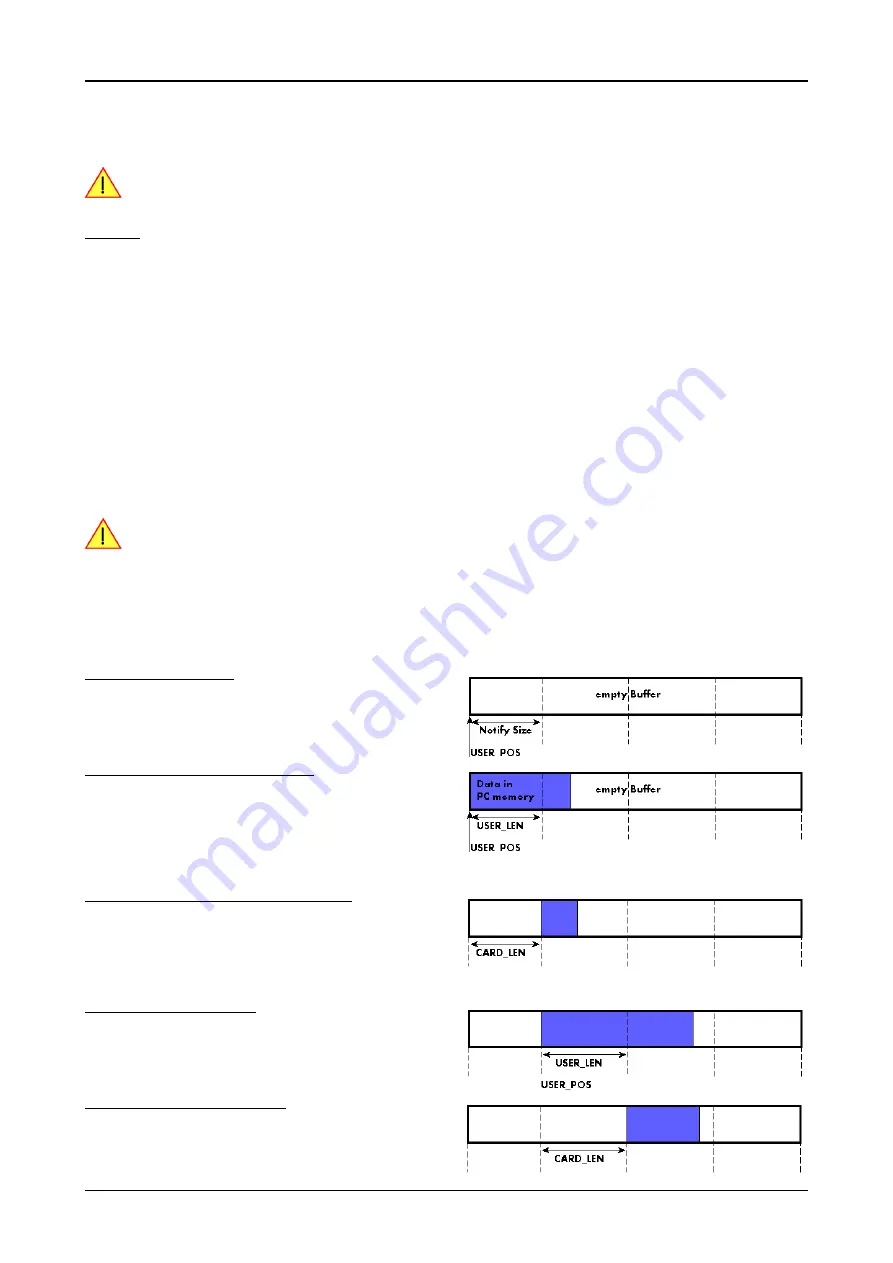
Step 1: Buffer definition
Directly after buffer definition the complete buffer is empty (card to PC) or
completely filled (PC to card). In our example we have a notify size which
is 1/4 of complete buffer memory to keep the example simple. In real
world use it is recommended to set the notify size to a smaller stepsize.
Step 2: Start and first data available
In between we have started the transfer and have waited for the first data
to be available for the user. When there is at least one block of notify size
in the memory we get an interrupt and can proceed with the data. Al-
though there is more data already transferred we only get announced to
have the notify size of data available. The USER_POS is still zero as we
are right at the beginning of the complete transfer.
Step 3: set the first data available for card
Now the data can be processed. If transfer is going from card to PC that
may be storing to hard disk or calculation of any figures. If transfer is go-
ing from PC to card that means we have to fill the available buffer again
with data. After this the amount of data is set available for the card and
for the next step.
Step 4: next data available
After reaching the next border of the notify size we get the next part of the
data buffer to be available. In our example this part of data is again only
of one notify size length. The user position will now be at the position [1
x notify size].
Step 5: set data available again
Again after processing the data we set it free for the card use.
In our example we now make something else and don’t react to the inter-
rupt for a longer time. In the background the buffer is filled with more da-
ta.


