background image

User Manual – Vehicle Tracker


Spectrum Embedded Solutions

©Copyright(2017)AllRightsReserved 

Page 6 of 6


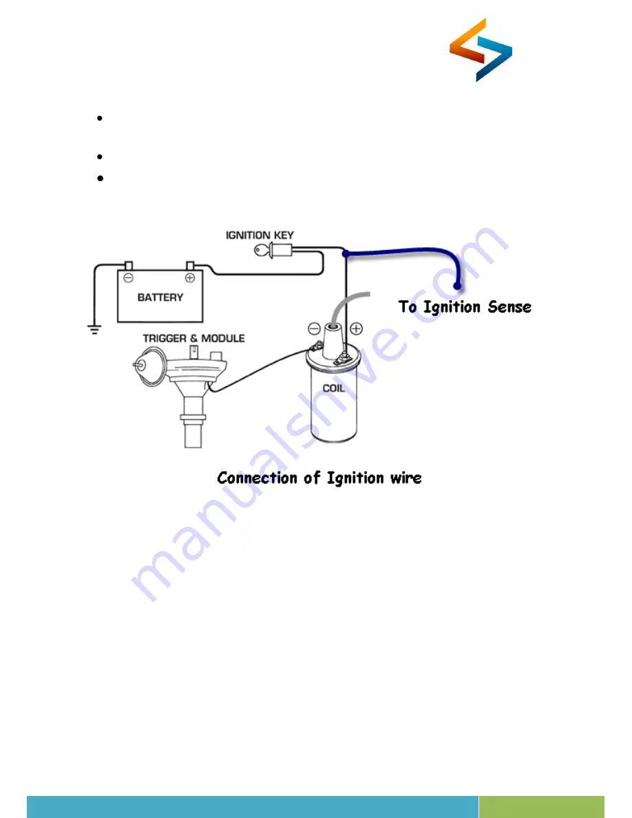
Connect the 

RED

 wire to the Positive (+) Terminal of the Battery and 

BLACK

 wire 

to the Negative (-) Terminal of the Battery. 


To sense the Ignition Connect the Blue wire. 


The wiring Diagram is shown below.


Summary of Contents for VT04

Page 1: ...VEHICLE TRACKER USER MANUAL VT04 ...

Page 2: ...tic Products VT04 is a well built robust vehicle tracker designed with authentic and astute methodology of tracking the vehicles for a better utilization and easy management of vehicles This VT04 can also operates on low power consumption mode that withstands up to 300 days for eminent tracking with live tracking location status tracing history playback on the map and report playback for speed dis...

Page 3: ...e Status and Alerts Fuel Level Sense Temperature Monitor Vehicle Battery Status 2 Digital Inputs 2 Digital Outputs and 2 Analog Inputs Configurable through SMS In built Embedded Antenna Low power consumption mode Tamper proof Vibration alert Low battery alert Over Speed Idle Time and Scheduled Alerts SMS and GPRS TCP communication Data logger mechanism during the un availability of GSM signal Down...

Page 4: ...perature 200 C to 550 C Humidity 5 to 95 Non condensing GSM Module Quad band 850 900 1800 1900 MHz SIM Type Normal SIM GPS Type AGPS GPS Sensitivity Acquisition 148dBm Tracking 165dBm Reacquisition 160dBm GPS Frequency L1 1575 42MHZ Channels 22 Tracking 66 Acquisition Position Accuracy 10 M 2D RMS Velocity Accuracy 0 1m s Acceleration Accuracy 0 1m s2 Timing Accuracy 1PPS Out 10ns Reacquisition 1s...

Page 5: ...h power devices such as reversing radar anti theft device or communication equipment would affect the signal of the device All metallic cases of the windshield will attenuate the signal on the tracking device It s simply due to the shielding effects of the metal compound of the case Product Wiring Information ...

Page 6: ...Solutions Copyright 2017 AllRightsReserved Page 6 of 6 Connect the RED wire to the Positive Terminal of the Battery and BLACK wire to the Negative Terminal of the Battery To sense the Ignition Connect the Blue wire The wiring Diagram is shown below ...

Page 7: ...t Every 1 sec 100ms On 900ms Off GPS Module has started obtaining Location data from satellite CHG STA RED Status Indication Continously Off Internal Battery Charging Completed Continously ON Internal Battery Charging Continues EXT SUPPLY GREEN Status Indication Continously Off External Power Supply Vehicle Battery Disconnected Continously ON External Power Supply Vehicle Battery Connected Install...

Page 8: ...sure the device is positionedstable The Device should be placed facing upwards Do not keep Device near High Temperature Flammable substance For better accuracy the device should be placed under direct sky visibility Ouraimistoprovideclient customerswithtimelyandcomprehensiveservice Forany assistance pleasecontact our company headquarters SpectrumEmbeddedSolutions 23 6 IVFloor Viswa Paradise Kalida...

Page 9: ...hts reserved No part of this document may be reproduced or by any means electronic mechanical photocopying recording or otherwise without the express written permission from Spectrum Embedded Solutions The information contained herein is subject to change without notice All other trademarks mentioned herein are the property of their respective owners ...

Reviews: