7 |
P a g e
7
DESCRIPTION & OPERATION
SECTION 1 Instruction Manual
DESCRIPTION OF OPERATION
Optical Loop Interface Unit
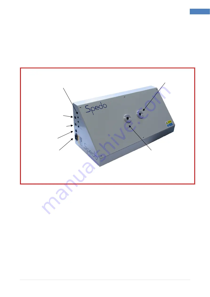
This unit consists of a box assembly with 2 optical sensors (fitted in the centre of the top cover), which
operate in conjunction with a opto sensing board inside the unit. The optical sensors detect the presence
of the paper loop between the outfeeding printer or unwinder and the infeeding forms cutter and
maintains it at a height set by the operator. It has a maximum height detection range of 300 mm, which
can be adjusted internally.
Fig 1.2 Identification of Main Parts
Operation with Ancillary Units
Optical Loop Interface Unit is supplied with mains power from the forms cutter by interconnecting it with
the mains lead supplied. The sync lead is also connected to the forms cutter. Several cables are provided
for interfacing with input devices and care must be taken to ensure the correct cable is used.
Both sensor have been factory set for optimum running conditions (300mm for the cutter control sensor
and 100mm for the printer control sensor) but these can be adjusted if necessary.(see page 9)
Printer Control Sensor
Cutter Control Sensor
Printer Interface Output
Mains Power Input
Fuse 800mA
Cutter Interface Output
Status Indicators


