background image


8 | 

P a g e


DESCRIPTION & OPERATION 

SECTION 1 Instruction Manual 

INSTALLATION 


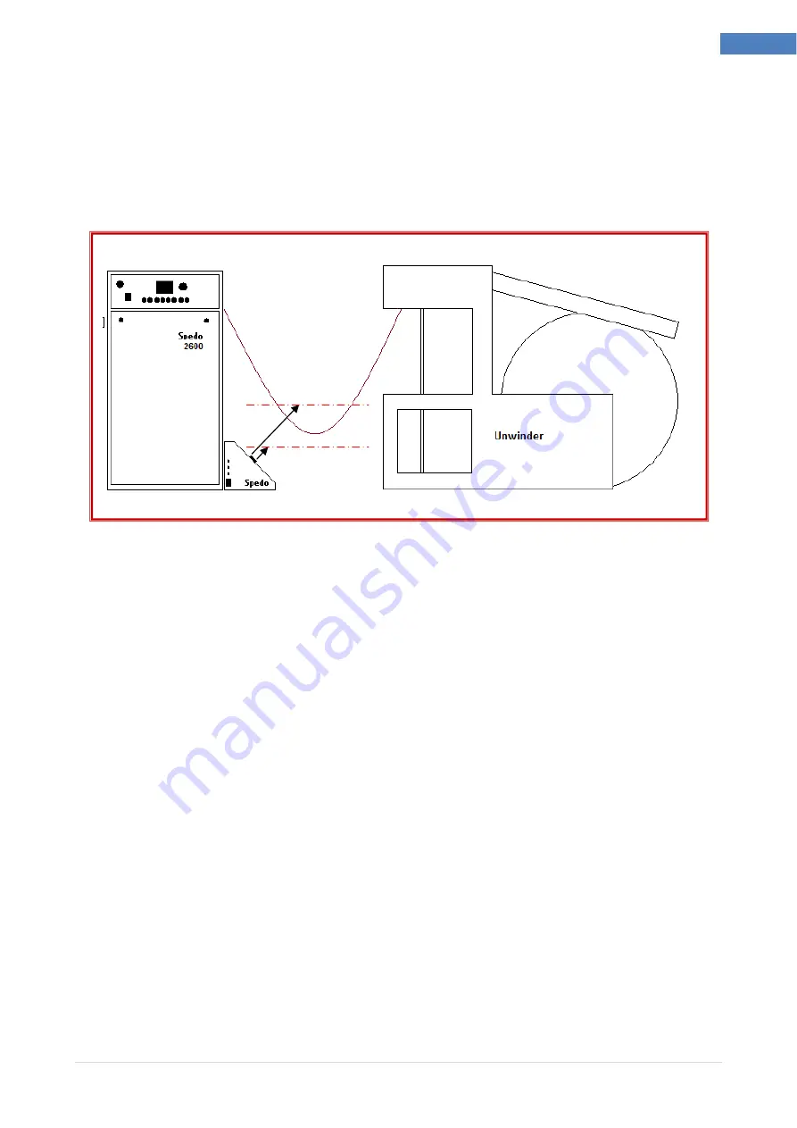
Position  optical  loop  box  in  front  of  the  cutter  so  that  both  sensors  are  aligned  with  the 
paper web. 


Ensure all cables are fitted to the corresponding plugs and tighten into position. 


Fig 1.3 Operating States 


Switch on the forms cutter. Check that the optical loop interface unit is now powered up and 
the ADEV RUN and the ADEV READY indicators are illuminated. 


Place a piece of paper in front of the cutter control sensor and check that, at a maximum of 
300  mm,  the  CUTTER  RUN  indicator  toggles  on  and  off  as  the  paper  is  moved  inside  and 
outside the sensing range. 


Place a piece of paper in front of the printer control sensor and check that, at a maximum of 
100mm the ADEV RUN indicator toggles on and off. Note: this output is on a time delay of 
approximately 2 seconds. This time delay can be adjusted as required. (see page 9). 


If the above check is satisfactory, the unit is ready to operate. 


Summary of Contents for Issue 2

Page 1: ...1 Spedo Optical Loop Interface 2232 Instruction Manual Spedo Optical Loop Interface 2232 Instruction Manual Issue 2 Spedo UK Limited 76 Woolmer Way Bordon Hampshire GU35 9QF ENGLAND Telephone 44 0 1420 487 447 Fax 44 0 1420 477 827 Email spedo spedouk com Web www spedouk com ...

Page 2: ... P a g e 2 Spedo Optical Loop Interface 2232 Instruction Manual Spedo Optical Loop Interface 2232 History Sheet Manual Issue Date Changes Incorporated 1 January 2013 First Issue 2 May 2015 Format Changed ...

Page 3: ...extent hereafter mentioned against defects arising from faulty material or workmanship subject to the goods not having suffered maltreatment or interference The Company s liability under this guarantee is limited to replacing any part or parts found defective within a period as laid down in Company instructions after the date of delivery or installation Other Goods If goods not of the Company s ma...

Page 4: ...lowed by the user to ensure safe operation and to retain the equipment in a SAFE condition All users of the equipment described in this manual MUST have received adequate training in its use and application in order to ensure SAFE AND PROPER USE Any adjustment maintenance or repair of the opened apparatus under voltage shall be carried out only by a skilled person who is AWARE OF THE HAZARD INVOLV...

Page 5: ...ight 3 Safety Measures 4 Table of Contents 5 DESCRIPTION AND OPERATION SECTION 1 INTRODUCTION 6 TECHNICAL DATA 6 DESCRIPTION OF OPERATION 7 Optical Loop Interface Unit 7 Operation with Ancillary Units 7 INSTALLATION 8 OPERATING INSTRUCTIONS 9 Paper Detection Range Adjustment 9 Printer Output Delay Adjustment 10 OPERATIONAL MAINTENANCE 11 ...

Page 6: ...orms cutter of other manufacture can be used provided it is fitted with a synchronisation input facility The unit is positioned on the floor mounted on 4 feet between the two units Fig 1 1 Spedo Optical Loop Switch 2232 TECHNICAL DATA Paper Loop Sync Switched relay contact normally open Closed across pins 1 3 when paper is detected Mains Power 240 V 10 50 60 Hz Mains Fuse 800 mA Type F800mA Dimens...

Page 7: ...be adjusted internally Fig 1 2 Identification of Main Parts Operation with Ancillary Units Optical Loop Interface Unit is supplied with mains power from the forms cutter by interconnecting it with the mains lead supplied The sync lead is also connected to the forms cutter Several cables are provided for interfacing with input devices and care must be taken to ensure the correct cable is used Both ...

Page 8: ... ADEV RUN and the ADEV READY indicators are illuminated Place a piece of paper in front of the cutter control sensor and check that at a maximum of 300 mm the CUTTER RUN indicator toggles on and off as the paper is moved inside and outside the sensing range Place a piece of paper in front of the printer control sensor and check that at a maximum of 100mm the ADEV RUN indicator toggles on and off N...

Page 9: ...ciated indicator are housed on the opto sensor assembly and can only be accessed from inside the unit With the mains power disconnected remove x6off M4x12 screws and carefully lift off the top cover Note this cover is attached to cables which connect directly to control board Fig 1 4 Paper Detection Range Adjustments The adjustment control and indicator are located at the end of the opto sensor Th...

Page 10: ... 5 With the mains power disconnected remove x6off M4x12 screws and carefully lift off the top cover Note this cover is attached to cables which connect directly to control board Fig 1 5 Printer Output Delay Adjustments Reconnect the mains power Adjust the potentiometer VR1 R8 on earlier models Test the reaction time of the printer control sensor by covering and uncovering and checking the delay on...

Page 11: ...s equipment Ensure that the equipment is isolated from the mains supply when carrying out any maintenance procedures Cleaning This is limited to removing the build up of paper dust with an airline from the face of the opto sensor This should be carried out on a regular basis Connectors Periodically check the connectors for bent or dirty pins ...

Reviews: