9 |
P a g e
9
DESCRIPTION & OPERATION
SECTION 1 Instruction Manual
OPERATING INSTRUCTIONS
WARNING:
Never operate the combined system when wearing items of loose clothing or
other decorative jewellery, such as necklaces or bracelets as they could become entrapped
in the ancillary machinery and cause injury.
Having checked the serviceability of the unit, as in Installation above, it may be required to
adjust the range of detection of the opto sensors for your particular system.
Paper Detection Range Adjustment
WARNING:
High voltage mains is present on this equipment. Ensure that the equipment is
isolated from the mains supply when carrying out any adjustments.
The adjustment control and associated indicator are housed on the opto sensor assembly
and can only be accessed from inside the unit.
With the mains power disconnected, remove x6off M4x12 screws and carefully lift off the
top cover.
Note: this cover is attached to cables which connect directly to control board.
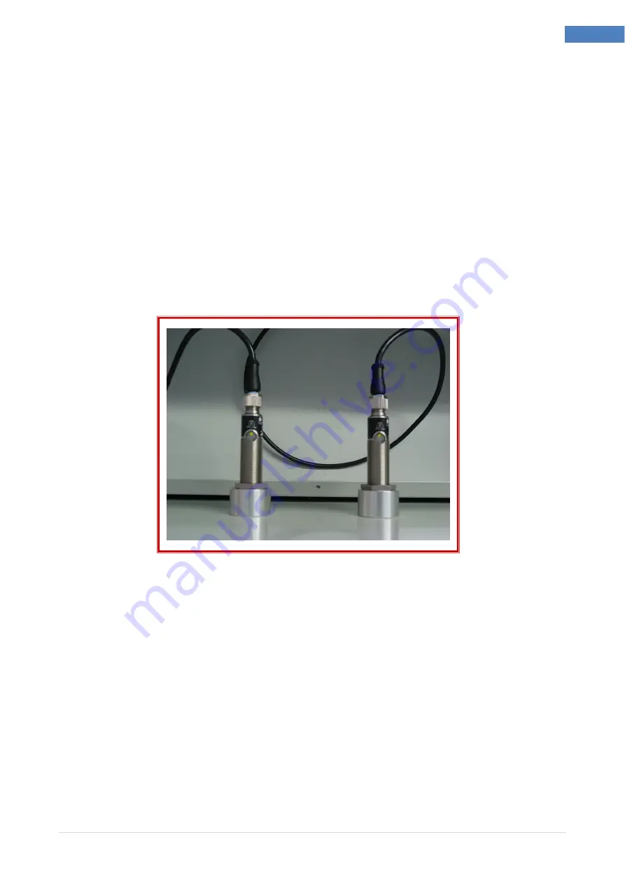
Fig 1.4 Paper Detection Range Adjustments
The adjustment control and indicator are located at the end of the opto sensor. The
indicator illuminates when paper is detected.
Reconnect the mains power. Place a piece of paper in front of the opto sensor. Adjust the
setting of the control, at the same time as moving the paper towards and away from the
front of the opto sensor, noting the distance at which the indicator lights. Vary the setting
until the required distance is reached.
Disconnect the mains power and refit the top cover.
Position the unit back into the system and reconnect it, ready to continue operation.


