9400000-J0 Rev C
24
7.6 Inserting the CXCM4 Module
NOTE:
Do not force a module into position if it does not seat properly. All modules are keyed to
ensure that the correct module (voltage/polarity) type is used.
1. Insert by placing the controller on the shelf bottom and sliding the module into the CXCM4 connection
interface (inside of the shelf, see drawing 747-271-08).
2. Apply pressure on the metal faceplate to engage the rear connectors.
3. Tighten the screw on the bottom of the faceplate to secure the module to the shelf.
7.7 Signal Wiring Connections for CXCM4
The CXCM4 (specifications 018-586-B1) requires an adapter for modular installation (drawing 747-271-08).
For terminal block connections, the recommended wire sizes are 0.823 to 0.129mm2 (#18 to #26 AWG) for the
temperature range of 0 to 50 deg. C (as per UL/CSA).
CAUTION!
To reduce risk of fire, use only 0.129 mm
²
(#26 AWG) or larger wire.
7.7.1 Relay Outputs
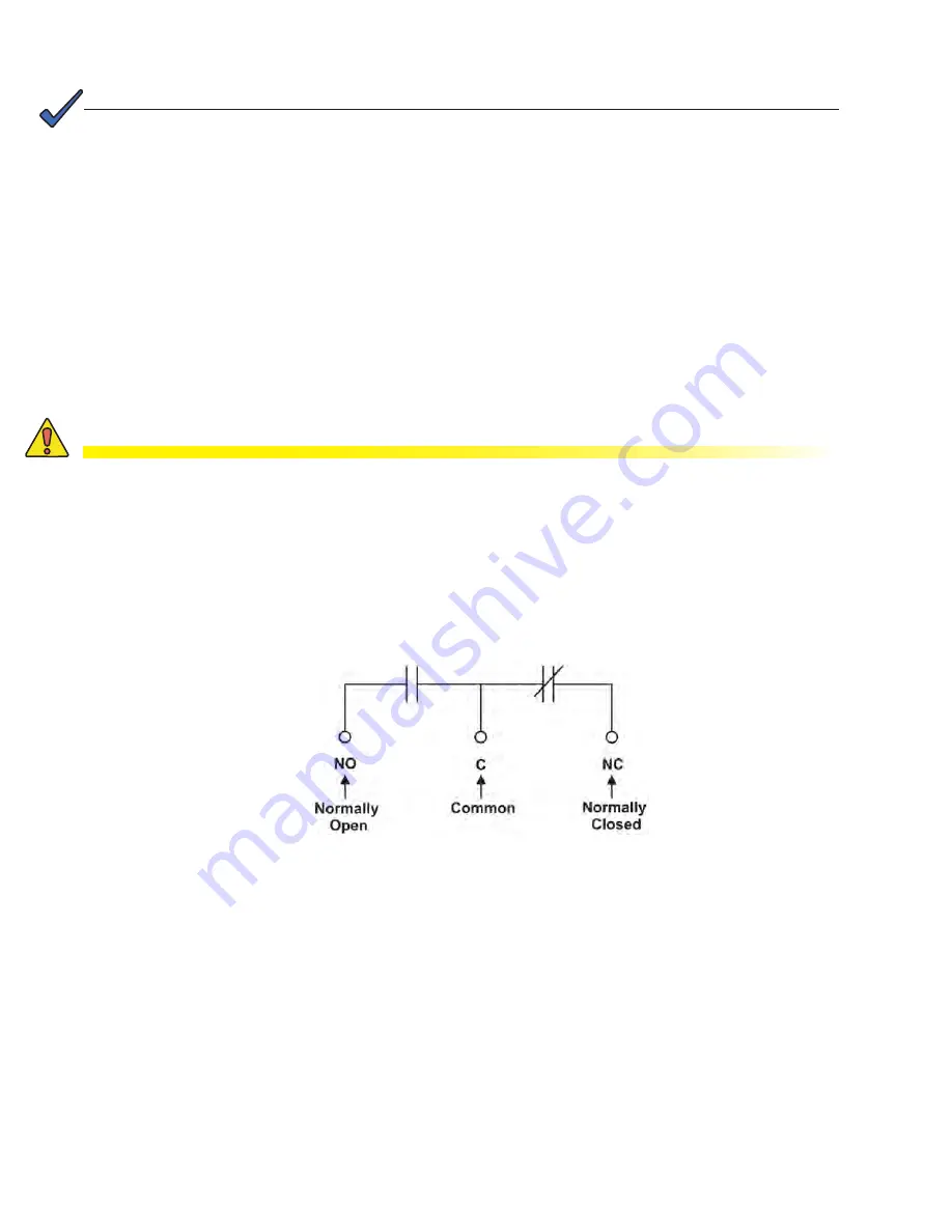
Terminals provide contacts for extending various alarm or control signals. Each relay output can be wired for NO
or NC operation during an alarm or control condition (Figure 12).
Figure 6 — Relay connections in the de-energized state
Relays can be programmed to energize or de-energize during an alarm condition (see CXC Software manual).
When the CXC reset button is pressed or power is lost, all relays de-energize.
System Fail Relay
The System Fail output relay (K0) is fail-safe and will de-energize during an alarm condition.
Low Voltage Disconnect (LVD) Control
The LVD control functions can be hard wired directly from the assigned relay output to an optional LVD override
control and distribution alarm card. This safety measure protects against load disconnect during CXCM4 reset or
replacement (see Section 10.3), e.g. when the controller is off-line. Operators can also perform test and mainte-
nance procedures on the CXCM4 without disturbing the load. See the Controls Menu defaults in the CXC Soft-
ware manual.


