background image

KINETIC LOG SPLITTER

ASSEMBLY & OPERATING INSTRUCTIONS

Owner’s Manual

Model Number

580899

WARNING: 

 All operators must read this manual before operating this log 

splitter. Follow the safety instructions in the manual and in decals attached 

to the product. Failure to do so could result in serious injury or death.

K1601

Summary of Contents for 580899

Page 1: ...ner s Manual Model Number 580899 WARNING All operators must read this manual before operating this log splitter Follow the safety instructions in the manual and in decals attached to the product Failure to do so could result in serious injury or death K1601 ...

Page 2: ......

Page 3: ...t 1 Safety Decals 2 General Safety 3 Work Area 3 Preparation of the Log 3 Operation of the Log Splitter 3 General Maintanence 4 Workplace Safety 4 Towing Safety 4 Assembly Instructions 5 13 Replacement parts 14 19 Operating Instructions 20 21 Towing 22 Warranty information 23 Specifications Back Cover ...

Page 4: ......

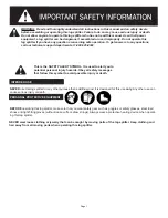
Page 5: ...ury or death PERSONAL PROTECTIVE EQUIPMENT INTENDED USE NEVER wear loose clothing or jewelry that can be caught by moving parts of the log splitter Keep clothing and hair away from all moving parts when operating this log splitter Page 1 WARNING Read and thoroughly understand all instructions in this manual and on safety decals before assembling or operating this log splitter Failure to do so may ...

Page 6: ...efaced decals Contact SpeeCo at 1 800 525 8322 for replacement decals PART NUMBER 580388 LOCATION TOP OF SHIELD PART NUMBER 580387 LOCATION TOP OF TONGUE PART NUMBER 581696 LOCATION TOP OF SHIELD PART NUMBER S52062500 LOCATION SIDE OF TOUNGE PART NUMBER S52069100 LOCATION FRONT OF SWING STAND 1 SIDES OF BEAM 2 Page 2 PART NUMBER 584052 LOCATION SIDE OF BEAM TOWARD REAR ...

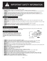
Page 7: ...ho stands in the operator zones using the hand closest to the log to operate the safety latch and the other hand to press the control handle Failure to operate the log splitter in this position can result in serious injury or death ALWAYS load the log onto the beam up against the wedge ALWAYS be careful when moving or lifting the log splitter Get help if unit is too heavy to move by yourself ALWAY...

Page 8: ... safety chains when towing your log splitter ALWAYS replace ball or coupler if damaged or excessively worn NEVER exceed 45 mph when towing your log splitter Towing the log splitter at speeds higher than 45 mph could result in loss of control damage to the equipment serious injury or death Adjust towing speed for terrain and condi tions ALWAYS be extra cautious when towing over rough terrain especi...

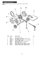
Page 9: ... 5 578705 TONGUE KINETIC ASM 1 6 580851 TABLE KINETIC SPEECO RED WDMT 1 7 575856 BELT GATES A74 2 8 581493 COVER BELT W DECAL KINETIC 1 9 581695 SHIELD SPEECO LEFT W DECAL KINETIC 1 10 581555 SHIELD SPEECO RIGHT W DECAL KINETIC 1 11 578723 HANDLE UPPER BLACK KINETIC ASM 1 ASSEMBLY INSTRUCTIONS NOTE Unpack the crate and check contents carefully before starting assembly Page 5 K1603 ...

Page 10: ...PS 1 4 20 X 1 1 4 8 7 2457 1 4NC x 3 4 HHCS GR5 4 8 5336 1 4 STD FLAT WASHER 8 9 1985 WASHER LOCK 1 4ID ZINC PLT STL 10 10 583332 NUT CNTOCK 1 4 20UNC X 7 32 GR2 2 11 570789 NUT HEX 1 4 20UNC X 7 32 GR5 2 BAG 580954 Part Description QTY 15 20973 BOLT CARRIAGE 3 8 16 X 1 1 4 GR5 Silver 4 16 584306 BOLT HEX 3 8 16X1 1 2 GRADE 8 Yellow 2 17 570793 NUT HEX 3 8 16UNC X 21 64 GR5 Silver 4 18 575805 NUT ...

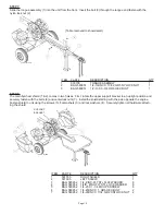
Page 11: ...utward Secure using the washers 2 and slotted nuts 3 Tighten slotted nut firmly on the axle spindle The wheel should be stiff to turn by hand then back the slotted nut off 1 3 to 1 2 turn Align slotted nut with hole in axle spindle and insert then bend cotter pin Install the dust cap ITEM PART DESCRIPTION QTY 1 S400312B0 TIRE 2 2 BAG 580955 3 4 FLAT WASHER 2 3 BAG 580955 3 4 IN 16 SL NF HEX NUT 2 ...

Page 12: ...ch pin 2 through the bottom holes in the beam and swing jack leg Install the R clip to secure pin ITEM PART DESCRIPTION QTY 1 578727 AXLE ASSEMBLY 1 2 BAG 580953 3 8 16X1 1 2 GRADE 8 HEX BOLT 4 3 BAG 580953 3 8ID ZINC PLT STL LOCK WASHER 4 4 BAG 580953 3 8 16UNC X 21 64 GR8 HEX NUT 4 5 581740 BEAM ASSEMBLY 1 ITEM PART DESCRIPTION QTY 1 581492 LEG 1 2 BAG 580951 1 2 X 4 1 4 SWIVEL HITCH PIN 1 3 BAG...

Page 13: ...lywheel while setting the belt tension STEP 5C Loop the two V belts 5 over the flywheel Install the belts into the v channels on the clutch pulley closest to the motor first STEP 5D In order to set the belt tension use the provided gauge which will set the belts at 60 pounds of tension Pull on the belt using the hook side of the gauge as shown below about an equal distance away from the flywheel a...

Page 14: ...is too tight and the tension must be decreased Move the engine towards the tires to decrease tension If the handle notches are below the edge then the belt is too loose and the tension must be increased Move the engine away from the tires to increase tension STEP 5F Repeat this measurement on the other belt tighten the engine mounting bolts and re check both belts to ensure that they are still at ...

Page 15: ...e 11 BELT COVER MOUNT LOCATIONS K1625 STEP 6 Move the table 4 into place by sliding table in from the front of the beam assembly Install the bolts 1 2 flat washer 7 lock washer 6 and nut 3 5 onto each bolt as installed and finger tighten all bolts Securely tighten all bolts ITEM PART DESCRIPTION QTY 1 BAG 580954 3 8 16 X 1 1 4 GR5 CARRIAGE BOLT 4 2 BAG 580954 3 8 16X1 1 2 GRADE 8 HEX BOLT 2 3 BAG ...

Page 16: ...81555 RIGHT SHIELD 1 2 581695 LEFT SHIELD 1 3 BAG 580952 1 4 ZINC PLT STL FLAT WASHER 8 4 BAG 580952 1 4ID ZINC PLT STL LOCK WASHER 8 5 BAG 580952 1 4 20 X 1 1 4 PHILIPS SCREW 8 6 BAG 580952 1 4 20UNC X 1 GR5 HEX BOLT 2 7 BAG 580952 1 4 20UNC X 7 32 GR2 CNTLOCK NUT 2 SUPPORT BRACKET K1628 STEP 7 Slide the tongue assembly 1 into the unit from the front Insert the bolt 3 through the tongue and faste...

Page 17: ... control handle 1 into position at the top of the unit Securely lock the handle in place by tightening down the locking nut on the control handle NOTES Page 13 ITEM PART DESCRIPTION QTY 1 578723 HANDLE ASEMBLY 1 K1629 ...

Page 18: ...ID ZINC PLT STL 14 584306 BOLT HEX 3 8 16X1 1 2 GRADE 8 15 572214 WASHER LRG 3 8ID 1 1 4OD ZINC ITEM PART DESCRIPTION 1 583470 BEAM BLACK W DECALS KINETIC 2 573519 BEARING PINION KINETIC 3 573539 PINION KINETIC SPLITTER 4 573540 BUMPER KINETIC SPLITTER 5 570789 NUT HEX 1 4 20UNC X 7 32 GR5 6 3093 3 8IN SHAKEPROOF LCKWASHER 7 584306 BOLT HEX 3 8 16X1 1 2 GRADE 8 8 577120 BOLT ELEVATOR 1 5 16DIA 3 8...

Page 19: ... 565275 BOLT HEX M10X1 5X100 GR5 6 S40032300 20 LINK CHAIN W HOOK 7 584307 NUT NYLOCK M10X1 5X10 CLS8 8 S52062500 TRILINGUAL DECAL TONGUE WARNING ITEM PART DESCRIPTION 1 583480 OVER CNT LINKAGE KINETIC SPLTR WDMT 2 575704 BEARING ROLLER 3 8ID 1 1 4OD 3 576757 BOLT SHOULDER 3 8 X 2 1 2 STL 4 838 WASHER LOCK 3 8ID ZINC PLT STL 5 574435 NUT NYLOCK 5 16 18UNC X 11 32 GR5 K1632 K1633 ...

Page 20: ...ORSION LEFT HANDLE 3 576032 SPRING TORSION RIGHT HANDLE ITEM PART DESCRIPTION 1 583490 AXLE 8IN KINETIC SPLITTER WDMT 2 581582 ENGINE KOHLER SH265 3 575523 CLUTCH KINETIC SPLITTER 4 S52029800 DECAL ASM IN THE USA 5 583491 KIT HARDWARE ENGINE KINETIC NOT INDICATED ON DRAWING K1634 K1635 ...

Page 21: ...ROOVED 1 2DIA 3 1 2LG 14 573524 SPRING RETURN KINETIC SPLITTER 15 2457 1 4 NC X 3 4 HHCS GR5 16 583332 NUT CNTLOCK 1 4 20UNC X 7 32 GR2 17 572670 FLYWHEEL KINETIC 18 574874 KEY STOCK 3 8 X 3 8 X 1 1 2 19 581797 SCREW SET SQ 5 16 18 X 1 1 2 20 576755 CLIP E STYLE 1 2 YELLOW ZINC STL 21 583483 MOUNT SPRING RETURN KINETIC 22 572230 NUT NYLOCK 3 8 16UNC X 29 64 GR5 23 574454 NUT NYLOCK FLANGE 3 8 16UN...

Page 22: ...TIC 8 580382 HANGTAG SPEECO KINETIC 9 580457 DECAL FEATURES KINETIC NOT SHOWN ITEM PART DESCRIPTION 1 S071011C0 1 2 X 4 1 4 SWIVEL HITCH PIN 2 576044 PIN GROOVED 1 2DIA 3 3 4LG 3 576755 CLIP E STYLE 1 2 YELLOW ZINC STL 4 584305 BOLT HEX 1 2 13 X 3 3 4 GR5 5 573552 NUT NYLOCK 1 2 13UNC X 19 32 GR5 ITEM PART DESCRIPTION 1 S40033200 CAP HI SPEED TIRE AND WHEEL 2 5849 3 4 NF SLOTTED HEX NUT 3 2864 3 4...

Page 23: ...T DESCRIPTION 1 S52069100 DECAL PINCH POINT ITEM PART DESCRIPTION 1 581696 DECAL LOCK HANDLE KINETIC 2 580388 DECAL HANDLE KINETIC NOTE After any parts replacemant verify the proper operation of the machine K1641 K1642 ...

Page 24: ...instruction for engine type and allow engine to come to full operating speed before using the unit NOTE When splitter is not in use turn fuel valve off per engine manufacturer s manual NOTE Soak the bronze clutch bushing in light weight oil at the start of every season and after every 100 hours of use Page 20 WARNING Read and thoroughly understand all instructions in this manual and on safety deca...

Page 25: ...ttle control to the SLOW or LOW idle position Turn the key switch or on off switch to OFF or move throttle to STOP position if equipped Close the fuel shut off valve ENGINE OPERATION SPLITTER OPERATION 1 Disconnect the log splitter if it is attached to a towing vehicle 2 Set up the log splitter in a clear level area and chock the wheels 3 Check for adequate oil and fuel supply Add as needed 4 Star...

Page 26: ...e lowered position and secure with R clip and pin Retract the tongue Page 22 This log splitter is equipped with pneumatic tires a Class I coupler 2 in diameter ball required and safety chains Before towing the safety chains must be secured to the hitch or bumper of the vehicle Local regulations should be checked regarding licensing lights towing etc Turn fuel shut off valve on the engine to the Of...

Page 27: ... on IMPORTANT NOTICE We the manufacturer reserve the right to change the product and or specification in this manual without notification The manual is for information usage only and the pictures and drawings depicted herein are for reference only Warranty Repair and Service Do not return this product to the store for warranty issues or repair Call 1 800 525 8322 or www speeco com for the location...

Page 28: ...NOTES ...

Page 29: ......

Page 30: ...Stand Flip Up Beam 4 x 4 Length 102 Width 49 Height 49 Weight 540 lbs Cycle time may vary dependent upon mechanical and environmental conditions 45 MPH Maximum road speed A Blount International Brand 16025 Table Mountain Parkway Suite 3 Golden CO 80403 1 800 525 8322 Email techsupport blount com Website www speeco com ...

Page 31: ...propietario Número de modelo 580899 ADVERTENCIA Todos los operadores deben leer este manual antes de operar este partidor de troncos Siga las instrucciones de seguridad del manual y las etiquetas adheridas al producto Si no lo hace podría causar lesiones graves o la muerte K1601 ...

Page 32: ......

Page 33: ...eral 3 Área de trabajo 3 Preparación de los troncos 3 Operación del partidor de troncos 3 Mantenimiento general 4 Seguridad en el lugar de trabajo 4 Seguridad del remolque 4 Instrucciones de ensamble 5 13 Piezas de reemplazo 14 19 Instrucciones de operación 20 21 Remolque 22 Información de servicio por garantía 23 Especificaciones Contraportada ...

Page 34: ......

Page 35: ...s NUNCA use este partidor de troncos para otros propósitos que no sean partir madera Está diseñado para este uso solamente Cualquier otro uso puede causar lesiones graves o la muerte EQUIPO DE PROTECCIÓN PERSONAL USO PREVISTO Página 1 ADVERTENCIA Lea y entienda completamente todas las instrucciones de este manual y en las calcomanías de seguridad antes de ensamblar u operar este partidor de tronco...

Page 36: ... 8322 si necesita calcomanías de reemplazo NÚMERO DE PIEZA 580388 UBICACIÓN PARTE SUPERIOR DEL PROTECTOR NÚMERO DE PIEZA 580387 UBICACIÓN PARTE SUPERIOR DE LA LENGÜETA NÚMERO DE PIEZA 581696 UBICACIÓN PARTE SUPERIOR DEL PROTECTOR NÚMERO DE PIEZA S52062500 UBICACIÓN PARTE LATERAL DE LA LENGÜETA NÚMERO DE PIEZA S52069100 UBICACIÓN PARTE DELANTERA DEL SOPORTE DE GIRO 1 LADOS DEL BRAZO 2 Página 2 NÚME...

Page 37: ...muerte SIEMPRE cargue el tronco en el brazo hacia arriba contra la cuña SIEMPRE sea cuidadoso al mover o levantar el partidor de troncos Pida ayuda si la unidad es muy pesada para que la mueva solo SIEMPRE acuñe las ruedas adecuadamente para evitar que el partidor de troncos se mueva durante la operación NUNCA coloque las manos las partes del cuerpo ni la ropa debajo de los protectores durante la ...

Page 38: ...e troncos SIEMPRE reemplace la bola o el acoplador si está dañado o muy desgastado NUNCA exceda 45 mph al remolcar su partidor de troncos Remolcar el partidor de troncos a velocidades mayores que 45 mph puede resultar en la pérdida de control daño al equipo lesiones graves o la muerte Ajuste la velocidad de remolque para el terreno y las condiciones SIEMPRE sea extremadamente precavido cuando remo...

Page 39: ...A CINÉTICA ENSAMBLE 1 6 580851 MESA CINÉTICA SPEECO RED WDMT 1 7 575856 CORREA ACCESO A74 2 8 581493 CUBIERTA CORREA CON ETIQUETA CINÉTICA 1 9 581695 PROTECTOR SPEECO IZQUIERDO CON ETIQUETA CINÉTICA 1 10 581555 PROTECTOR SPEECO DERECHO CON ETIQUETA CINÉTICA 1 11 578723 MANIJA SUPERIOR NEGRA CINÉTICA ENSAMBLE 1 INSTRUCCIONES DE ENSAMBLE NOTA Desempaque la caja y revise cuidadosamente su contenido a...

Page 40: ...CS GR 5 4 8 5336 ARANDELA PLANA ESTÁNDAR DE 1 4 8 9 1985 ARANDELA BLOQUEO 1 4 DI ACERO GALVANIZADO 10 10 583332 CONTRATUERCA BLOQUEO 1 4 20 UNC X 7 32 GR 2 2 11 570789 TUERCA HEXAGONAL 1 4 20 UNC X 7 32 GR 5 2 BOLSA 580954 Pieza N Descripción CTD 15 20973 PERNO CARRO 3 8 16 X 1 1 4 GR 5 plateado 4 16 584306 PERNO HEXAGONAL 3 8 16X1 1 2 GRADO 8 amarillo 2 17 570793 TUERCA HEX 3 8 16 UNC X 21 64 GR ...

Page 41: ...ete la tuerca ranurada firmemente en el husillo del eje La rueda debe estar dura como para girarla con la mano entonces afloje la tuerca de 1 3 a 1 2 vuelta Alinee la tuerca ranurada con el agujero en el husillo del eje e inserte posteriormente el pasador de chaveta doblado Instale la tapa contra polvo PASO 3 Coloque el ensamble del eje de nuevo en la caja con las ruedas anidadas entre las dos ban...

Page 42: ... brazo y la pata oscilante del gato Instale el sujetador R para asegurar el pasador ARTÍCULO PIEZA N DESCRIPCIÓN CTD 1 578727 ENSAMBLE DE EJE 1 2 BOLSA 580953 TORNILLO HEX DE GRADO 8 DE 3 8 16X1 1 2 4 3 BOLSA 580953 ARANDELA DE BLOQUEO DE ACERO GALVANIZADO DE 3 8 DE DI 4 4 BOLSA 580953 TUERCA HEXAGONAL GR 8 DE 3 8 16UNC X 21 64 4 5 581740 ENSAMBLE DE BRAZO 1 ARTÍCULO PIEZA N DESCRIPCIÓN CTD 1 5814...

Page 43: ... con el volante mientras ajusta la tensión de la correa PASO 5C Abroche las dos correas en V 5 sobre el volante Instale las correas en los canales en V sobre la polea del embrague lo más cerca a primera del motor PASO 5D Para ajustar la tensión de la correa use el medidor que ajuste la correa a 60 libras de tensión Jale la correa usando el lado del gancho del medidor como se muestra abajo alrededo...

Page 44: ... la correa está demasiado apretada y se debe disminuir la tensión Mueva el motor hacia los neumáticos para disminuir la tensión Si las muescas de la manija están debajo del borde entonces la correa está demasiado floja y se debe aumentar la tensión Mueva el motor lejos de los neumáticos para aumentar la tensión PASO 5F Repita esta medición en la otra correa apriete los pernos de montaje del motor ...

Page 45: ...AJE DE LAS CUBIERTAS DE LAS CORREAS K1625 ARTÍCULO PIEZA N DESCRIPCIÓN CTD 1 BOLSA 580954 PERNO DE CARRO 3 8 16 X 1 1 4 GR 5 4 2 BOLSA 580954 PERNO HEXAGONAL DE 3 8 16 X 1 1 2 GRADO 8 2 3 BOLSA 580954 TUERCA HEXAGONAL 3 8 16 UNC X 21 64 GR 8 2 4 580851 MESA 1 5 BOLSA 580954 TUERCA HEXAGONAL 3 8 16 UNC X 21 64 GR 5 4 6 BOLSA 580954 ARANDELA DE BLOQUEO ACERO GALVANIZADO 3 8 DI 6 7 BOLSA 580954 ARAND...

Page 46: ...ECTOR IZQUIERDO 1 3 BOLSA 580952 ARANDELA PLANA DE ACERO GALVANIZADO 1 4 8 4 BOLSA 580952 ARANDELA DE BLOQUEO ACERO GALVANIZADO 1 4 DI 8 5 BOLSA 580952 TORNILLO PHILIPS 1 4 20 X 1 1 4 8 6 BOLSA 580952 PERNO HEXAGONAL 1 4 20 UNC X 1 GR 5 2 7 BOLSA 580952 TUERCA CNTLOCK 1 4 20 UNC X 7 32 GR 2 2 SOPORTE ANGULAR K1628 PASO 7 Deslice el ensamble de la lengüeta 1 en la unidad desde el frente Inserte los...

Page 47: ...ol 1 en posición en la parte superior de la unidad Asegure la manija de seguridad en su lugar apretando la tuerca de bloqueo sobre la manija de control NOTAS Página 13 ARTÍCULO PIEZA N DESCRIPCIÓN CTD 1 578723 ENSAMBLE DE MANIJA 1 K1629 ...

Page 48: ...4 580386 ETIQUETA PROTECTOR ADVERTENCIA CINÉTICA 15 1033176 ETIQUETA DEL NOMBRE DE PLACA DE NÚMERO DE SERIE 16 584052 ETIQUETA PROP QUÍMICAS 65 K1630 K1631 ARTÍCULO PIEZA N DESCRIPCIÓN 1 583477 CARA PLACA DE EMPUJE NEGRA WDMT 2 583478 PLACA BASE PRESIÓN PLACA WDMT 3 575625 PLACA PLACA DE DESGASTE CINÉTICO 4 575639 PLACA COJINETE PLACA DE PRESIÓN 5 583479 PLACA DESCONEXIÓN PLACA DE PRESIÓN 6 575660...

Page 49: ...O HEXAGONAL M10X1 5X100 GR 5 6 S40032300 CADENA DE 20 ESLABONES CON GANCHO 7 584307 TUERCA NYLOCK M10X1 5X10 CLS8 8 S52062500 ETIQUETA TRILINGÜE ADVERTENCIA LENGÜETA ARTÍCULO PIEZA N DESCRIPCIÓN 1 583480 SOBRE CNT ESLABÓN CINÉTICO PARTIDOR WDMT 2 575704 COJINETE RODILLO 3 8 DI 1 1 4 DE 3 576757 PERNO RESALTO 3 8 X 2 1 2 ACERO 4 838 ARANDELA BLOQUEO 3 8 DI ACERO GALVANIZADO 5 574435 TUERCA NYLOCK 5...

Page 50: ...ERDO MANIJA 3 576032 RESORTE TORSIÓN DERECHO MANIJA ARTÍCULO PIEZA N DESCRIPCIÓN 1 583490 EJE 8 PULG CINÉTICO PARTIDOR WDMT 2 581582 MOTOR KOHLER SH265 3 575523 EMBRAGUE CINÉTICO PARTIDOR 4 S52029800 ETIQUETA ENSAMBLADO EN LOS EE UU 5 583491 KIT TORNILLERÍA MOTOR CINÉTICO NO SE INDICA EN EL DIBUJO K1634 K1635 ...

Page 51: ... 2 LG 14 573524 RESORTE RETORNO CINÉTICO PARTIDOR 15 2457 1 4NC x 3 4 HHCS GR 5 16 583332 CONTRATUERCA BLOQUEO 1 4 20 UNC X 7 32 GR 2 17 572670 VOLANTE CINÉTICO 18 574874 PIEZAS PRINCIPALES 3 8 X 3 8 X 1 1 2 19 581797 TORNILLO FIJACIÓN CUADRADO 5 16 18 X 1 1 2 20 576755 CLIP E ESTILO 1 2 AMARILLO ZINC STL 21 583483 MONTAJE RESORTE RETORNO CINÉTICO 22 572230 TUERCA NYLOCK 3 8 16 UNC X 29 64 GR 5 23...

Page 52: ...NETIC 9 580457 ETIQUETA F UNCIONES CINÉTICA NO SE MUESTRA ARTÍCULO PIEZA N DESCRIPCIÓN 1 S071011C0 PASADOR DE CHAVETA DE 1 2 PULG X 4 1 4 PULG 2 576044 PASADOR RANURADO DIÁ 1 2 3 3 4 LG 3 576755 CLIP E ESTILO 1 2 AMARILLO ZINC STL 4 584305 PERNO HEX 1 2 13 X 3 3 4 GR 5 5 573552 TUERCA NYLOCK 1 2 13 UNC X 19 32 GR 5 ARTÍCULO PIEZA N DESCRIPCIÓN 1 S40033200 TAPA LLANTA Y RUEDA DE ALTA VELOCIDAD 2 58...

Page 53: ...069100 ETIQUETA PUNTO DE ESTRICCIÓN ARTÍCULO PIEZA N DESCRIPCIÓN 1 581696 ETIQUETA BLOQUEO MANIJA CINÉTICA 2 580388 ETIQUETA MANIJA CINÉTICA NOTA Después de reemplazar cualquier pieza verifique el funcionamiento adecuado de la máquina K1641 K1642 ...

Page 54: ...de motor y deje que el motor alcance la velocidad total de operación antes de usar la unidad NOTA Cuando no esté usando el partidor cierre la válvula de combustible de acuerdo al manual del fabricante del motor NOTA Remoje el cojinete de bronce del embrague en aceite liviano al inicio de cada estación y después de cada 100 horas de uso Página 20 ADVERTENCIA Lea y entienda completamente todas las i...

Page 55: ...urador DETENER EL MOTOR De ser posible retire la carga Mueva el control del acelerador a la posición de ralentí SLOW lento o LOW bajo Gire el interruptor de la llave o el interruptor on off encendido apagado a off apagado o mueva el acelerador a la posición STOP parar si está incluido Cierre la válvula de cierre de combustible OPERACIÓN DEL MOTOR OPERACIÓN DEL PARTIDOR 1 Desconecte el partidor de ...

Page 56: ...o y asegure con el sujetador R y el pasador Retraiga la lengüeta Página 22 El partidor de troncos está equipado con llantas neumáticas un acoplador Clase I se requiere una bola de 2 pulg de diámetro y cadenas de seguridad Antes de remolcar las cadenas de seguridad se deben asegurar al enganche o a la defensa del vehículo Debe revisar las regulaciones locales respecto a la concesión de licencias lu...

Page 57: ...ORTANTE Nosotros el fabricante nos reservamos el derecho de cambiar el producto o las especificaciones en este manual sin ninguna notificación El manual es solo para uso informativo y las imágenes y diagramas aquí contenidos son únicamente para referencia Reparación y servicio por garantía No devuelva este producto a la tienda por problemas de garantía ni reparación Llame al 1 800 525 8322 o www s...

Page 58: ...NOTAS ...

Page 59: ......

Page 60: ...ntado Brazo 4 pulg x 4 pulg Longitud 102 pulg Ancho 49 pulg Altura 49 pulg Peso 540 lb El tiempo del ciclo puede variar dependiendo de las condiciones mecánicas y ambientales 45 mph de velocidad máxima en carretera Una marca de Blount International 16025 Table Mountain Parkway Suite 3 Golden CO 80403 1 800 525 8322 Correo electrónico techsupport blount com Sitio web www speeco com ...

Page 61: ...580899 AVERTISSEMENT Tous les opérateurs doivent lire ce manuel avant d utiliser cette fendeuse de bûches Suivre les consignes de sécurité fournies dans ce manuel et sur les autocollants apposés sur le produit Le non respect de ces consignes peut entraîner des blessures graves voire mortelles K1601 ...

Page 62: ......

Page 63: ...rale 3 Zone de travail 3 Préparation des bûches 3 Utilisation de la fendeuse de bûches 3 Entretien général 4 Sécurité de l environnement de travail 4 Sécurité du remorquage 4 Instructions de montage 5 13 Pièces de rechange 14 19 Instructions d utilisation 20 21 Remorquage 22 Informations relatives à la garantie 23 Caractéristiques techniques Au dos du manuel ...

Page 64: ......

Page 65: ...hes Ne JAMAIS utiliser cette fendeuse de bûches à d autres fins que celle de fendre du bois Elle a été conçue pour ce seul et unique usage Un usage à toute autre fin peut entraîner des blessures graves voire mortelles ÉQUIPEMENT DE PROTECTION INDIVIDUELLE USAGE PRÉVU Page 1 AVERTISSEMENT Lire et bien comprendre toutes les instructions de ce manuel et des autocollants de sécurité avant de monter ou...

Page 66: ...ter SpeeCo au 1 800 525 8322 pour obtenir des autocollants de rechange N DE RÉF 580388 EMPLACEMENT SUR LE CARTER N DE RÉF 580387 EMPLACEMENT SUR LA FLÈCHE N DE RÉF 581696 EMPLACEMENT SUR LE CARTER N DE RÉF S52062500 EMPLACEMENT CÔTÉ DE LA FLÈCHE N DE RÉF S52069100 EMPLACEMENT AVANT DU SUPPORT RABATTABLE 1 CÔTÉS DU PLATEAU 2 Page 2 N DE RÉF 584052 EMPLACEMENT CÔTÉ DU PLATEAU VERS L ARRIÈRE CONSIGNE...

Page 67: ...a bûche et appuie sur le levier de commande de l autre main Se placer ailleurs pour utiliser la fendeuse peut entraîner des blessures graves voire mortelles TOUJOURS charger la bûche sur le plateau contre le coin de fendage TOUJOURS faire attention lorsque l on déplace ou soulève la fendeuse de bûches Se faire aider si l unité est trop lourde pour être déplacée à une personne TOUJOURS caler correc...

Page 68: ... boule ou l attelage s ils sont endommagés ou trop usés NE JAMAIS remorquer la fendeuse de bûches à plus de 45 mph Le remorquage de la fendeuse de bûches à des vitesses supérieures à 45 mph peut entraîner une perte de contrôle endommager l équipement ou provoquer des blessures graves voire mortelles Adapter la vitesse de remorquage au terrain et aux conditions TOUJOURS redoubler de prudence lors d...

Page 69: ...580851 TABLE SPEECO ROUGE FENDEUSE CINÉTIQUE SOUD 1 7 575856 COURROIE GATES A74 2 8 581493 PROTECTEUR DE COURROIES AVEC AUTOCOLLANT FENDEUSE CINÉTIQUE 1 9 581695 CARTER SPEECO GAUCHE AVEC AUTOCOLLANT FENDEUSE CINÉTIQUE 1 10 581555 CARTER SPEECO DROIT AVEC AUTOCOLLANT FENDEUSE CINÉTIQUE 1 11 578723 LEVIER SUPÉRIEUR NOIR FENDEUSE CINÉTIQUE 1 INSTRUCTIONS DE MONTAGE REMARQUE Déballer la palette et en...

Page 70: ...OULON D ASSEMBLAGE À TÊTE HEXAGONALE 1 4 NC X 3 4 GR 5 4 8 5336 RONDELLE PLATE 1 4 STANDARD 8 9 1985 RONDELLE FREIN 1 4 D I EN ACIER GALVANISÉ 10 10 583332 ÉCROU DE BLOCAGE 1 4 20 UNC X 7 32 GR 2 2 11 570789 ÉCROU HEX 1 4 20 UNC X 7 32 GR 5 2 SACHET 580954 Nº réf Description QTÉ 15 20973 BOULON DE CARROSSERIE 3 8 16 X 1 1 4 GR 5 argent 4 16 584306 BOULON HEX 3 8 16 X 1 1 2 GR 8 jaune 2 17 570793 É...

Page 71: ... ont pas été endommagés BLOC DE SUPPORT K1649 K1652 ÉTAPE 1 Poser la palette sur un sol plat dans un espace dégagé pour le montage Retirer le dessus de la palette et le mettre de côté Enlever tous les objets de la palette Localiser les sacs de boulonnerie 580955 et 580953 dans la boîte de boulonnerie ÉTAPE 2 Retirer les roues de leur emballage d expédition Retirer les capots de protection en plast...

Page 72: ... trous inférieurs dans la poutre et le pied pivotant à béquille Installer le clip en R pour fixer la goupille ÉLÉMENT Nº RÉF DESCRIPTION QTÉ 1 578727 ENSEMBLE ESSIEU 1 2 SAC 580953 BOULON HEX 3 8 IN 16 X 1 1 2 IN CALIBRE 8 4 3 SAC 580953 RONDELLE DE BLOCAGE ACIER GALVANISÉ D I 3 8 4 4 SAC 580953 ÉCROU HEX 3 8 16 UNC X 21 64 CALIBRE 8 4 5 581740 ENSEMBLE POUTRE 1 ÉLÉMENT Nº RÉF DESCRIPTION QTÉ 1 58...

Page 73: ...age de tension des courroies ÉTAPE 5C Positionner les deux courroies trapézoïdales 5 sur le volant Installer les courroies dans les gorges trapézoïdales de la poulie d embrayage en commençant par la plus proche du moteur ÉTAPE 5D Pour régler la tension des courroies utiliser la jauge fournie qui définit la tension des courroies à 60 lbs Tirer sur la courroie à l aide du côté crochet de la jauge co...

Page 74: ... à nouveau la tension des courroies pour s assurer qu elle est toujours correcte UNE COURROIE TROP TENDUE ENTRAÎNE UNE USURE ET UNE DÉFAILLANCE PRÉMATURÉES DE L EMBRAYAGE ET PEUT CAUSER UNE USURE DE L ARBRE MOTEUR K1618 K1620 K1619 K1622 K1621 K1623 K1624 ÉTAPE 5E Tirer lentement avec un mouvement régulier sur la courroie à l aide de la jauge jusqu à ce que les encoches du côté crochet soient alig...

Page 75: ...ACEMENTS DE MONTAGE DU PROTECTEUR DE COURROIES K1625 ÉTAPE 6 Mettre la table 4 en place en la glissant depuis l avant du plateau Insérer les boulons 1 et 2 une rondelle plate 7 une rondelle frein 6 et un écrou 3 et 5 sur chaque boulon installé et serrer tous les boulons à la main Serrer fermement tous les boulons ÉLÉMENT Nº RÉF DESCRIPTION QTÉ 1 SACHET 580954 BOULON DE CARROSSERIE 3 8 16 X 1 1 4 G...

Page 76: ...ARTER DROIT 1 2 581695 CARTER GAUCHE 1 3 SACHET 580952 RONDELLE PLATE 1 4 EN ACIER GALVANISÉ 8 4 SACHET 580952 RONDELLE FREIN 1 4 D I EN ACIER GALVANISÉ 8 5 SACHET 580952 VIS CRUCIFORME 1 4 20 X 1 1 4 8 6 SACHET 580952 BOULON HEX 1 4 20 UNC X 1 GR 5 2 7 SACHET 580952 ÉCROU DE BLOCAGE 1 4 20 UNC X 7 32 GR 2 2 K1628 SUPPORT ÉTAPE 7 Insérer la flèche 1 dans l unité en la glissant depuis l avant Insér...

Page 77: ...le levier de commande 1 en position sur le dessus de l unité Verrouiller fermement le levier en place en serrant l écrou de blocage situé dessus REMARQUES Page 13 ÉLÉMENT Nº RÉF DESCRIPTION QTÉ 1 578723 LEVIER 1 K1629 ...

Page 78: ... AUTOCOLLANT D AVERTISSEMENT CARTER FENDEUSE CINÉTIQUE 15 1033176 AUTOCOLLANT PLAQUE SIGNALÉTIQUE 16 584052 AUTOCOLLANT PRODUITS CHIMIQUES PROP 65 ÉLÉMENT Nº RÉF DESCRIPTION 1 583477 FACE DE PLAQUE DE POUSSÉE NOIRE SOUD 2 583478 SOCLE DE PLAQUE DE POUSSÉE SOUD 3 575625 PLAQUE D USURE DE SOCLE FENDEUSE CINÉTIQUE 4 575639 PLAQUE D APPUI DE PLAQUE DE POUSSÉE 5 583479 PLAQUE D ARRÊT DE PLAQUE DE POUSS...

Page 79: ...5 X 100 GR 5 6 S40032300 CHAÎNE À 20 MAILLONS AVEC CROCHET 7 584307 ÉCROU NYLOC M10 X 1 5 X 10 GR 8 8 S52062500 AUTOCOLLANT D AVERTISSEMENT TRILINGUE FLÈCHE K1632 K1633 ÉLÉMENT Nº RÉF DESCRIPTION 1 583480 BIELLETTE À ARC BOUTEMENT FENDEUSE CINÉTIQUE SOUD 2 575704 ROULEMENT À ROULEAUX 3 8 D I 1 1 4 D E 3 576757 BOULON À ÉPAULEMENT 3 8 X 2 1 2 EN ACIER 4 838 RONDELLE FREIN 3 8 D I EN ACIER GALVANISÉ...

Page 80: ...EVIER GAUCHE 3 576032 RESSORT DE TORSION LEVIER DROIT ÉLÉMENT Nº RÉF DESCRIPTION 1 583490 ESSIEU 8 IN FENDEUSE CINÉTIQUE SOUD 2 581582 MOTEUR KOHLER SH265 3 575523 EMBRAYAGE FENDEUSE CINÉTIQUE 4 S52029800 AUTOCOLLANT ÉTATS UNIS 5 583491 JEU DE BOULONNERIE MOTEUR FENDEUSE CINÉTIQUE NON ILLUSTRÉ K1634 K1635 ...

Page 81: ...ORT DE RAPPEL FENDEUSE CINÉTIQUE 15 2457 BOULON D ASSEMBLAGE À TÊTE HEXAGONALE 1 4 NC X 3 4 GR 5 16 583332 ÉCROU DE BLOCAGE 1 4 20 UNC X 7 32 GR 2 17 572670 VOLANT FENDEUSE CINÉTIQUE 18 574874 CLAVETTE EN BARRE 3 8 X 3 8 X 1 1 2 19 581797 VIS DE PRESSION À TÊTE CARRÉE 5 16 18 X 1 1 2 20 576755 CLIP E STYLE 1 2 JAUNE ZINC STL 21 583483 PATTE DE FIXATION DE RESSORT DE RAPPEL FENDEUSE CINÉTIQUE 22 57...

Page 82: ... ÉTIQUETTE VOLANTE SPEECO FENDEUSE CINÉTIQUE 9 580457 AUTOCOLLANT CARACTÉRISTIQUES FENDEUSE CINÉTIQUE NON ILLUSTRÉ ÉLÉMENT Nº RÉF DESCRIPTION 1 S071011C0 AXE D ATTELAGE À POIGNÉE 1 2 FT X 4 1 4 IN 2 576044 AXE À RAINURES 1 2 DE DIAM X 3 3 4 DE LARGE 3 576755 CLIP E STYLE 1 2 JAUNE ZINC STL 4 584305 BOULON HEX 1 2 13 X 3 3 4 GR 5 5 573552 ÉCROU NYLOC 1 2 13 UNC X 19 32 GR 5 ÉLÉMENT Nº RÉF DESCRIPTI...

Page 83: ...NT POINT DE PINCEMENT ÉLÉMENT Nº RÉF DESCRIPTION 1 581696 AUTOCOLLANT LEVIER DE VERROUILLAGE FENDEUSE CINÉTIQUE 2 580388 AUTOCOLLANT LEVIER FENDEUSE CINÉTIQUE REMARQUE Vérifier le bon fonctionnement de la machine après tout remplacement de pièce K1641 K1642 ...

Page 84: ...pement électrique une fendeuse de bûches peut s avérer dangereuse si elle n est pas montée ou utilisée correctement Ne pas utiliser cette fendeuse si l on a des questions quant à son utilisation en toute sécurité Pour obtenir des réponses à ses questions contacter notre service d assistance technique au 1 800 525 8322 K1643 K1644 REMARQUE Installer la fendeuse de bûches dans une zone plane et déga...

Page 85: ...lent et FAST accéléré L activation de l étrangleur est généralement inutile sur un moteur chaud ARRÊT DU MOTEUR Si possible retirer la charge Placer la commande des gaz en position de ralenti SLOW lent ou LOW grand ralenti Tourner le contacteur à clé ou de démarrage arrêt en position OFF arrêt ou placer la commande des gaz en position STOP arrêt le cas échéant Fermer la vanne d arrêt de carburant ...

Page 86: ...fixer avec la goupille de sécurité et l axe Rétracter la flèche Page 22 Cette fendeuse de bûches est équipée de pneus d un attelage de classe I boule de 2 in de diamètre requise et de chaînes de sécurité Avant le remorquage les chaînes de sécurité doivent être fixées à l attelage ou au pare chocs du véhicule Vérifier les réglementations locales relatives à l immatriculation à l éclairage au remorq...

Page 87: ...NT Nous le fabricant nous réservons le droit de modifier le produit et ou les caractéristiques décrits dans ce manuel sans préavis Le manuel n a qu une valeur informative et les illustrations et dessins qu il contient sont fournis à titre de référence uniquement Services et réparations sous garantie Ne pas retourner ce produit en magasin pour des questions de garantie ou pour réparation Pour trouv...

Page 88: ...REMARQUES ...

Page 89: ......

Page 90: ......

Page 91: ......

Page 92: ...port Rabattable Plateau 4 in x 4 in Longueur 102 in Largeur 49 in Hauteur 49 in Poids 540 lbs Le temps de cycle peut varier en fonction des conditions mécaniques et environnementales Vitesse sur route maximum de 45 MPH Une marque de Blount International 16025 Table Mountain Parkway Suite 3 Golden CO 80403 États Unis 1 800 525 8322 E mail techsupport blount com Site Internet www speeco com ...

Reviews: