Page 8
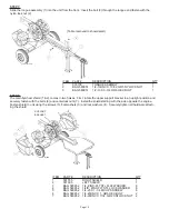
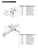
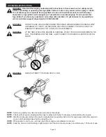
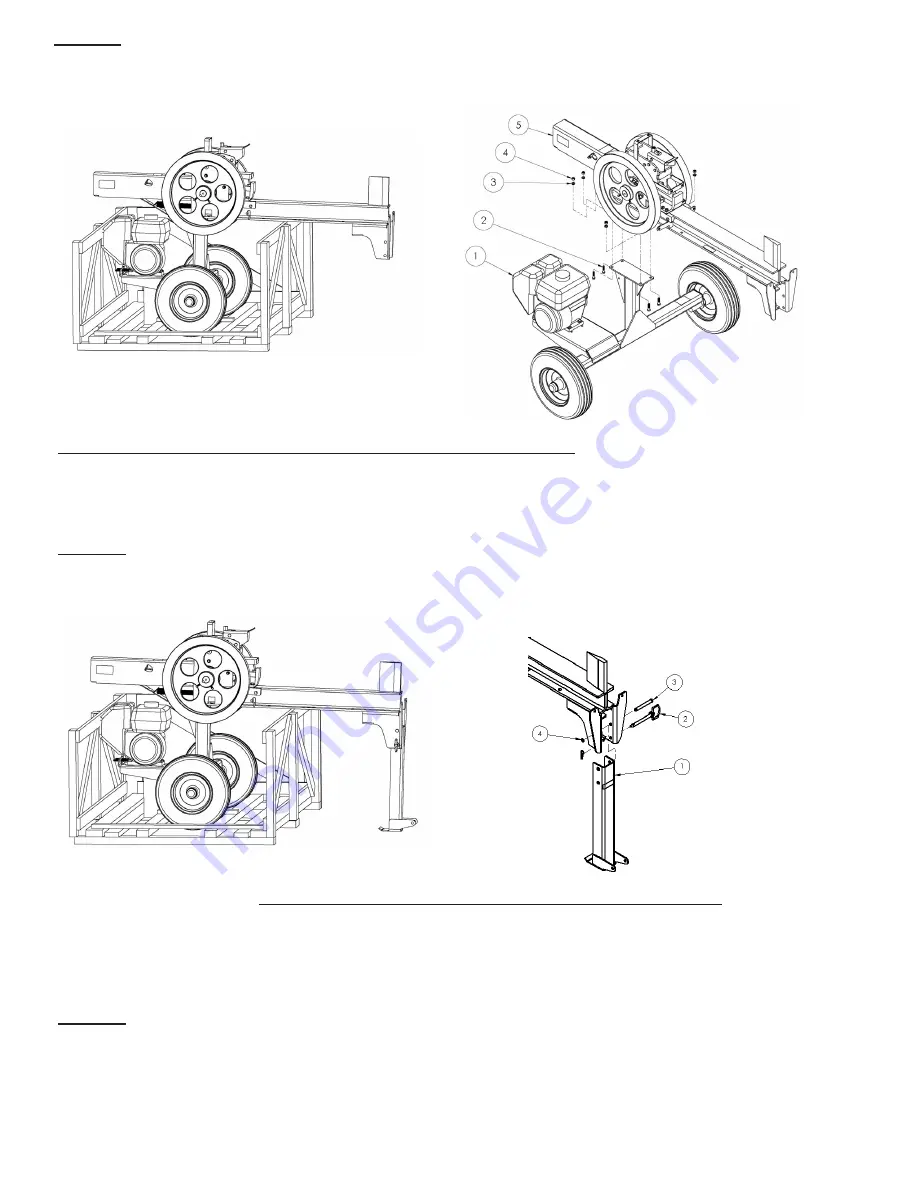
STEP 4A:
Lift the beam (5) and place it into position aligning the bolt holes of the axle assembly (1) with the mounting bolt holes of
the beam assembly. Part of the beam will overhang the crate and will be supported by the side of the crate. Install the
bolts (2), lock washers (3) and nuts (4). Tighten all four bolts securely.
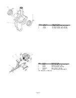
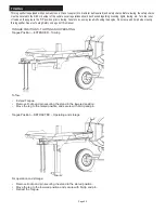
STEP 4B:
Install the swing leg (1) in the lowered position. Install the pin (3) with the snap ring (4) through the top hole. Install the
hitch pin (2) through the bottom holes in the beam and swing jack leg. Install the R-clip to secure pin.
ITEM
PART
#
DESCRIPTION
QTY
1 578727
AXLE
ASSEMBLY
1
2
BAG 580953 3/8-16X1-1/2, GRADE 8 HEX BOLT
4
3
BAG 580953 3/8ID, ZINC-PLT STL LOCK WASHER
4
4
BAG 580953 3/8-16UNC X 21/64, GR8 HEX NUT
4
5 581740
BEAM
ASSEMBLY
1
ITEM
PART
#
DESCRIPTION
QTY
1 581492
LEG
1
2
BAG 580951 1/2’ X 4 1/4” SWIVEL HITCH PIN
1
3
BAG 580951 1/2DIA, 3-3/4LG GROOVED PIN
1
4
BAG 580951 CLIP, E-STYLE, 1/2, YEL-ZINC STL
1
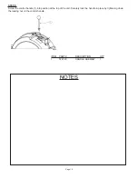
STEP 4C:
Raise the axle-beam assembly high enough that the crate can be removed and discarded. Lower the splitter to the
ground for the final assembly.
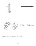
K1650
K1651
K1653
K1654
Summary of Contents for 580899
Page 2: ......
Page 4: ......
Page 28: ...NOTES ...
Page 29: ......
Page 32: ......
Page 34: ......
Page 58: ...NOTAS ...
Page 59: ......
Page 62: ......
Page 64: ......
Page 88: ...REMARQUES ...
Page 89: ......
Page 90: ......
Page 91: ......


