background image

10

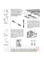
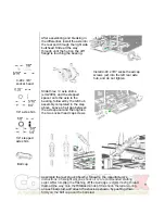
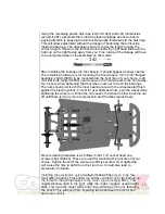
Find the steering knuckles (smr1281)(x2), front 
axles (smr1289)(x2) and E-clips (smr2092)(x2). 
Install an E-clip into the groove on the axle, then 
press fit the axle into the steering block threaded 
end first. Press the axle all the way through the 
steering block till the E-clip bottoms on the steering 
block. Using a 3/32” drill, open the indicated hole on 
the tabs of both steering blocks. Thread in the short 
neck ball studs (smr2069), secured by 4-40 mini-
hex nuts (smr2076), use thread lock on the stud.

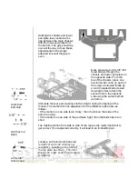
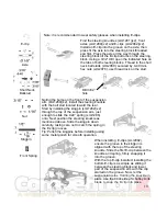
Noting the bump on the front of the suspension 
arm (smr1289)(x2), install the steering knuckle 
with the ball stud located toward the rear.
Start by installing the kingpin (smr1282)(x2) 
through the top of the suspension arm, just 
enough to slide the .022” spring (smr1286) 
onto. Next position the steering knuckle as 
mentioned above. Slide the kingpin down 
carefully, taking care not to catch the spring in 
the E-clip grooves.
Tip: Polish the kingpins before installing using 
some metal polish for smooth operation.

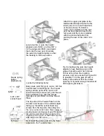
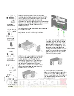
When installing  E-clips (smr2092), 
ensure the groove in the kingpin is 
aligned with the top of the steering 
knuckle. Slide the first E-clip between the 
knuckle and spring, firmly snapping it 
into the groove.
With the top E-clip installed, installing the 
bottom E-clip is as simple as sliding it 
between the steering block and lower 
part of the suspension arm with the clip 
started on the groove. Now, let the 
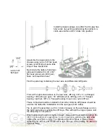
suspension relax. Holding the knuckle in 
place, use the back side of a hobby knife 
blade to snap the E-clip into place.

Drill 3/32” 
hole

Note: it is recommended to wear safety glasses when installing E-clips.

E-clip 

Axle 

Short Neck 
Ballstud 

Nut 

Kingpin 

Front Spring 

Summary of Contents for Speed Spec Pan Sedan

Page 1: ...difference in the handling of the car out on the track Required tools and supplies 050 Hex driver 1 16 Hex driver 3 32 Hex driver 5 64 Hex driver 3 16 Nut driver Nut driver 3 32 Nut driver File Cyano...

Page 2: ...hen filing the slots file from the top side of the chassis with the file at a 45 angle Have an assembled 4 cell battery pack handy to check depth as the chassis is filed Removing too much material wil...

Page 3: ...ts x2 smr2076 Attach the antenna mount smr1432 and front body mounts smr1551 to the chassis using 4 40 x 3 8 flat head screws x2 Install 4 40 aluminum ball stud into rear of the antenna mount using a...

Page 4: ...uts x2 smr2078 Slide center pivot assembly onto the 4 40 screws and secure with 4 40 lock nuts x2 smr2082 Attach the left and right bulkheads to the lower pod plate with 4 40 x 1 4 flat head screws x5...

Page 5: ...and will be fine tuned later Next place two 4 40 x 3 8 flat head screws smr2012 through the chassis and lower pod plate From the top of the chassis place one low roll center cone smr5008 on each of th...

Page 6: ...the same method as before Articulate the rear pod twisting it left and right noting the feeling of the motion The method for fine adjustment for the different actions are as follows If the motion on o...

Page 7: ...it is possible Trim the gate off with a hobby knife and test fit in the milled opening Only sand enough material off till the parts just slide in Locate the following items Body posts smr1551 x2 4 40...

Page 8: ...ring 3 8 x flanged bearing right hub 3 8 x flanged bearing thrust cone nylon diff nut These components will be installed in that order Silicone diff grease should be used on the balls after installat...

Page 9: ...hub assembly completed in the step above Leave a hair gap between the axle spacer and then tighten the two socket head cap screws located on the left hub Assemble the rear shock absorber following the...

Page 10: ...de the 022 spring smr1286 onto Next position the steering knuckle as mentioned above Slide the kingpin down carefully taking care not to catch the spring in the E clip grooves Tip Polish the kingpins...

Page 11: ...servo saver that matches your servo not included Make sure to retain the screw that came on the splined output shaft of the servo to attach the servo saver 8 32 Flat Head Screw Caster ride height shi...

Page 12: ...ross the chassis should be the same line for both holes as the servo should be mounted square to the chassis Drill two 1 8 holes and countersink the holes from the bottom side of the chassis with an 8...

Page 13: ...tening the front wheel nuts not to crush the bearings The nuts should just touch the inner bearing race with the wheel seated flush against the steering block To test for over tightened nuts spin the...

Reviews: