34
SPEKTRUM NX6 • TRANSMITTER INSTRUCTION MANUAL
EN
If you want to be able to assign the output channel to respond on
a curve or act as a switch, the Curve mix option will enable you
to move the output channel to any value at up to 7 points along
the travel of the input channel. Below the curve values, select a
channel for master control on the left and slave on the right. For
example, Throttle > Rudder makes Throttle the master channel
and Rudder the slave channel.
A channel monitor at the bottom of the screen shows how
channels respond to input during setup. To view a mix on the
monitor, the mix switch must be in the active position or the switch
set to ON.
Trim
If the master channel trim should also adjust the slave channel, set
Trim to Act.
Curve
The Curve value corresponds to each page of values assigned to
a switch position. Leave the Curve value matching the highlighted
box below the switch position for a basic configuration.
Switch
Select the switch you wish to use to activate the mix. The black
box indicates the switch position where the currently displayed
curve page is active, and the tick below the boxes indicates the
current switch position.
Select ON if you wish to activate the mix full time and do not want
to use a switch.
Tip:
Use Auto Switch Select to select the switch.
CAUTION:
Always do a Control Test of your model after
changing mixes.
Curve Mix
Curve (Page) Advanced Configuration Options
The Curve selection in either Normal or Curve mixes can enable
you to set up to 9 different settings pages. Curve settings within
one mix do not carry over to other mixes. This can be useful if you
want to test mixes and not have delete current configurations, or
can come into play when using numerous flight modes, with this
option there can be a separate mix page for each flight mode.
To select the page you want to adjust:
1. Assign the switch and begin with your first switch position.
2. Scroll to the Curve option and change the value to the number
you want for that Curve (page).
3. Scroll to the box above the active switch position and press
the scroll wheel to assign the Curve (page) to that switch
position.
4. Move the switch(es) to the next position you want to
configure, select the Curve (page) you want to use, and repeat
the process.
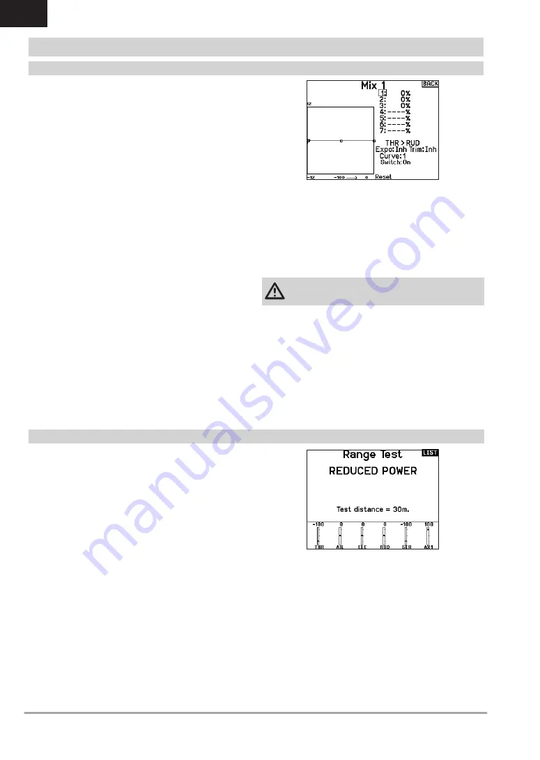
The Range Test function reduces the power output. This allows for
a range test to confirm the RF link is operating correctly. Perform
a range check at the beginning of each flying session to confirm
system operation.
To Access the Range Test screen:
1. With the transmitter on and the main or telemetry screen
displayed, press the scroll wheel. The Function list displays.
2. Scroll to highlight Range Test, then press the scroll wheel to
access the Range Test function.
3. With the Range Test screen displayed, push and hold the
trainer button. The screen displays Reduced Power. In this
mode the RF output is reduced allowing for an operational
range test of your system.
4. If you let go of the trainer button, the transmitter will go back
to Full Power.
IMPORTANT:
Telemetry alarms are disabled during the Range
Test.
Range Testing the NX6
1. With the model restrained on the ground, stand 30 paces
(approx. 90 feet/28 meters) away from the model.
2. Face the model with the transmitter in your normal flying
position and place the transmitter into Range Test mode (see
above). Then push the trainer button; the power output will be
reduced.
3. Operate the controls. You should have total control of your
model with the transmitter in Range Test mode.
4. If control issues occur, contact the appropriate Horizon Prod-
uct Support office for assistance.
5. If performing a range test while a telemetry module is active,
the display will show flight log data.
Range Test
FUNCTION LIST


