DXM100 MANUAL
13
118147-001 Rev. D
Chapter 4
P
RINCIPLES
O
F
O
PERATION
he DXM100 Series of high voltage power supplies
utilizes sophisticated power conversion technology.
Advanced analog and power conversion techniques
are used in the DXM100 series. The intention of the
Principles of Operation is to introduce the basic function
blocks that comprise the DXM100 power supply. For
details on a specific circuit, consult Spellman’s
Engineering Department.
The DXM100 power supply is basically an AC to DC
power converter. Within the power supply, conversions
of AC to DC then to high frequency AC, then to high
voltage DC take place.
Typical DXM100 power supplies comprise a few basic
building blocks. These are: 1) AC to DC rectifier, 2)
Power Factor correction boost circuitry 3) High frequency
quasi-resonant inverter, 4) High voltage transformer and
rectifier circuits, and 5) Control and monitoring circuits.
The following is a brief description of each building
block.
4.1 Power Factor and Associated
Circuits
The DXM100 series can operate from 180 - 265VAC.
The input voltage is connected via a typical IEC 320 type
input connector. An internal EMI filter and fuse housing
is an integral part of the DXM100 module. The input
circuits actively correct the power factor.
The input line voltage is applied to a current limit device
to reduce the initial inrush current. The input line voltage
is converted to a 400VDC voltage via an active PFC
Converter.
WARNING
The energy levels used and generated by the
power supply can be lethal! Do not attempt to
operate the power supply unless the user has a
sufficient knowledge of the dangers and hazards
of working with high voltage. Do not attempt to
approach or touch any internal or external
circuits or components that are connected or
have been connected to the power supply. Be
certain to discharge any stored energy that may
be present before and after the power supply is
used. Consult IEEE recommended practices for
safety in high voltage testing #510-1983.
4.2 High Frequency Inverter
The DXM100 is a resonant converter operating in a zero
current switching, series resonant, parallel loaded
topology. MOSFET transistors switch the 400 VDC
voltage to the resonant tank circuit. Typical operating
frequency is in the range of 35-65kHz depending on
model. Control of the resonant circuit output is done by
the low voltage control circuits, and are isolated by an
isolated pulse transformer. The output of the resonant
circuit is applied to the primary of the high voltage
transformer.
4.3 High Voltage Circuits
The high voltage transformer is a step-up type. The
secondary of the high voltage transformer is connected to
the high voltage rectifier circuit. The rectifier circuit will
vary depending upon the rated output voltage. For lower
power a half wave Cockroft-Walton multiplier is used, for
higher power a full wave Cockroft-Walton multiplier is
used. A feedback signal is generated by the high voltage
resistor divider. This feedback signal is sent to control
circuits to provide voltage regulation and monitoring. A
current sense resistor is connected at the low voltage end
of the rectifier circuit. The circuit sense signal is sent to
the control circuits to provide current regulation and
monitoring.
The high voltage rectifier output is connected to the
output limiting resistors. These resistors limit the peak
surge current in the event an arc or discharge occurs. The
limiting resistor output is connected to the output
connector provided.
T
Summary of Contents for DXM100 Series
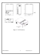
Page 11: ...DXM100 MANUAL 5 118147 001 Rev D Figure 2 1 Unit Dimensions ...
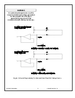
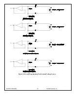
Page 16: ...DXM100 MANUAL 10 118147 001 Rev D Figure 3 3 Local Programming Via External Voltage Source ...
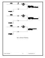
Page 17: ...DXM100 MANUAL 11 118147 001 Rev D Figure 3 4 Remote Monitoring ...
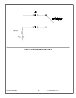
Page 18: ...DXM100 MANUAL 12 118147 001 Rev D RELAY Figure 3 5 Enable Interlock Logic Control ...
Page 37: ...118142 001 Rev B Page 13 of 104 Figure 9 Web Page 1 Contact Information ...

