SL SERIES MANUAL
24
118006-001 REV Y
Remote
Power
Program
3
4
2
-
M
1
V
-
TB1
Remove internal
jumper, JP1 ON
Control/Pwr PWB
for remote
Programing. (Jumper
connects internal,
pot, factory set at
103% of max power).
Remote
Power
Monitor
0-10V
=0-100%
power
output
Zout=
4.99k ohm 0.1%
20K ohm
min.
Z in = 10M ohm
7
13
6
12
5
+
+
Remote Power
Programming
potentiometer
M
1
2
high voltage
return circuits.
Pin 2 internally
connected to
pow er supply
chassis.
* IMPORTANT: Pow er dissipation
in CR1 should not exceed 1/2W.
This can be accomplished by
keeping TB3-1 and TB3-2
voltage below Zener voltage.
CR1 is f or saf ety and transient
protection only, and is not
designed f or continuous clamping.
Possible FG termination circuits
TB2
CR1
units are
shipped w ith
external
Up to 50V is available.
Consult f actory.
To internal
FG option
jumper.
Zener voltage is 18V standard.
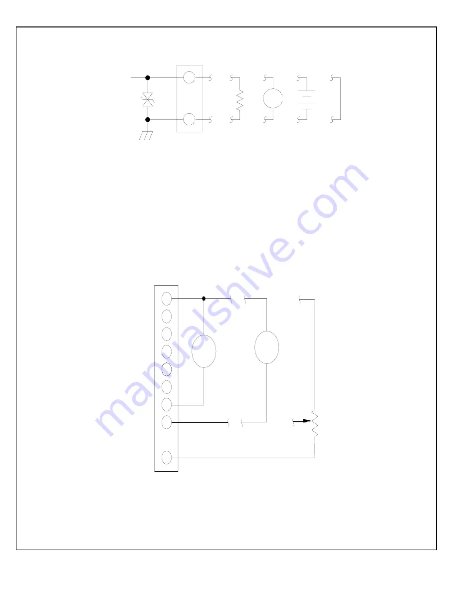
Figure 5.1 -- Floating Ground Interface Circuit
Figure 5.2 -- Adjustable Power Remote Interface TB1 Only


