EVA
Manual
20
118144
‐
001
REV.
A
Chapter
6
EVA
BEAM
CONTROLLER
INTRODUCTION
6.1
Description
of
Beam
Controller
(Filament
Power
Supply)
Multiple
beam
control
units
can
be
provided,
allowing
1,
2
or
3
separate
electron
guns
to
be
independently
operated
from
a
single
EVA
high
voltage
power
supply.
Each
beam
control
unit
consists
of
a
beam
controller
and
a
gun
output
box.
The
beam
controller
is
a
1U
(1.75”/44.45mm)
rack
‐
mounted
chassis
containing
the
filament
power,
control
and
emission
(beam)
current
regulation
circuitry.
The
gun
output
box
contains
the
high
frequency
filament
transformer
which
is
referenced
to
the
high
voltage
output
potential.
This
box
should
be
mounted
close
to
the
electron
gun
to
minimize
the
length
of
the
high
current
filament
connections.
The
box
also
contains
emission
(beam)
current
monitoring
circuitry
and
provides
a
feedback
signal
used
to
regulate
the
emission
(beam)
current.
Each
beam
control
channel
if
operated
alone
can
utilize
0
to
100%
of
the
rated
emission
current
capacity
of
the
EVA
high
voltage
power
supply.
When
two
or
three
beam
control
channels
are
used
at
the
same
time,
the
total
system
emission
current
capacity
remains
the
same.
Individual
channel
programming
must
be
done
such
that
the
total
current
does
not
exceed
the
systems
total
emission
current
available.
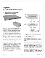
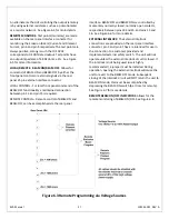
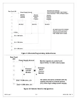
Figure
6.1
EVA
System
Block
Diagram
6.2
Standard
Features
The
beam
controller
incorporates
several
standard
features
designed
to
optimize
user
utility,
satisfaction
and
safety.
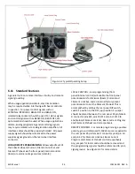
FRONT
PANEL
BEAM
OFF/
BEAM
ON
SWITCHES
:
These
intuitive
front
panel
controls
allow
the
user
to
easily
enable/disable
the
generation
of
the
electron
beam.
FRONT
PANEL
INDICATOR
LAMPS
:
BEAM
ON
and
BEAM
OFF
indicators
are
integral
with
the
control
switches
and
are
LED
illuminated
for
reliability
and
long
service
life.
FRONT
PANEL
POTENTIOMETERS
:
A
ten
turn
potentiometer
is
provided
for
easy
programming
of
the
desired
emission
(beam)
current
value.
Additionally
a


