EVA
Manual
21
118144
‐
001
REV.
A
single
turn
potentiometer
is
provided
for
the
Filament
Limit
Set
value.
FRONT
PANEL
DIGITAL
METERS
:
3.5
digit
meters
are
provided
to
view
the
Emission
(Beam)
Current,
Filament
Limit
Set
value
and
Filament
Operating
Current.
A
convenient
Preset
View
Feature
is
provided:
If
the
BEAM
OFF
button
is
depressed
and
held
in,
the
emission
(beam)
current
programming
value
will
be
displayed
in
mA
on
the
right
front
panel
meter.
Additionally
when
the
BEAM
OFF
button
is
depressed
and
held
in,
the
Filament
Limit
Set
value
will
be
displayed
in
amps
on
the
left
front
panel
meter.
When
in
the
active
BEAM
ON
condition
this
meter
displays
the
operational
filament
current
value.
INTERNAL
FAULT
PROTECTION
:
The
beam
controller
continually
monitors
internal
circuits
critical
to
its
operation.
If
one
of
these
circuits
malfunctions,
the
fault
detection
circuit
turns
off
the
emission
(beam)
current
and
reverts
the
unit
to
the
POWER
DOWN
mode,
where
neither
the
BEAM
ON
nor
the
BEAM
OFF
indicator
lamps
will
be
illuminated.
The
applicable
fault
indicator
will
be
illuminated
on
the
fault
diagnostic
panel,
requiring
the
user
to
clear
(depress
the
BEAM
OFF
switch,
or
cycle
the
AC
line
power)
before
the
emission
(beam)
current
can
be
re
‐
enabled.
6.3
Remote
Operating
Features
REMOTE
PROGRAMMING
:
Allows
remote
adjustment
of
the
Emission
(beam)
Current,
Filament
PreHeat
and
Filament
Limit
Set
parameters
via
the
use
of
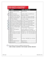
0
‐
10Vdc
=
0
‐
100%
rated,
external
voltage
sources.
REMOTE
MONITOR
:
Allows
remote
monitoring
of
the
0
‐
10Vdc
=
0
‐
100%
rated,
Emission
(beam)
Current
and
Filament
Current
test
points.
REMOTE
BEAM
ON/OFF
CONTROL
:
Allows
remote
control
of
the
BEAM
ON
and
BEAM
OFF
functions
via
dry
contact
opens
and
closures.
Signals
are
also
provided
for
remote
indication
of
BEAM
ON
and
BEAM
OFF
status.
EXTERNAL
INTERLOCK
:
Interlock
connections
are
provided
on
the
rear
panel
interface
connecter
for
connection
to
a
safety
switch.
The
unit
will
not
operate
unless
the
interlock
circuit
is
closed.
During
operation,
opening
the
interlock
circuit
will
cause
the
BEAM
ON
to
shut
off.
This
circuit
should
be
used
for
safety
interlock
circuits.
Spellman
strongly
recommends
the
use
of
External
Interlocking
for
safety
purposes.
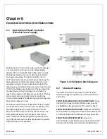
6.4
System
Status
and
Fault
Diagnostic
Display
“Dead
Front”
backlight
type
indicators
provide
system
operation
and
fault
condition
information.
If
a
fault
occurs
the
beam
controller
will
revert
to
the
POWER
DOWN
mode.
This
is
indicated
by
the
BEAM
ON
and
the
BEAM
OFF
indicator
lamps
both
not
being
illuminated.
The
applicable
fault
indicator
will
be
illuminated
on
the
front
panel
requiring
the
user
to
clear
(depress
the
BEAM
OFF
switch,
or
cycle
the
AC
line
power)
before
the
beam
can
be
re
‐
enabled.
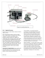
GUN
1
:
Indicates
a
beam
controller
is
active
in
the
Channel
One
position.
GUN
2
:
Indicates
a
beam
controller
is
active
in
the
Channel
Two
position.
GUN
3
:
Indicates
a
beam
controller
is
active
in
the
Channel
Three
position.
INTLK
CLOSED
:
Indicates
the
EXTERNAL
INTERLOCK
connections
are
in
the
closed
position.
INTLK
OPEN
:
Indicates
the
EXTERNAL
INTERLOCK
connections
are
in
the
open
position.
This
also
indicates
opening
of
internal
power
supply
interlocks.
It
is
not
possible
to
enable
BEAM
ON
with
an
open
EXTERNAL
INTERLOCK.


