EVA
Manual
22
118144
‐
001
REV.
A
RMT
CNTRL
:
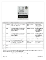
Indicates
that
the
programming
of
the
unit
is
being
accomplished
by
either
the
Ethernet
or
RS
‐
232
digital
interface.
This
feature
is
selectable
via
the
rear
panel
DIP
switch,
switch
position
1.
See
the
section
on
Configuration
for
more
details.
FIL
LIMIT
:
Indicates
that
the
beam
controller
is
limiting
the
filament
current
at
the
programmed
Filament
Current
Limit
level.
OVER
mA
:
Indicates
the
emission
(beam)
current
has
been
actively
limited
to
105%
of
maximum
rated
current
(as
per
an
internal
printed
circuit
board
potentiometer
setting).
FAULT
1
:
Not
allocated.
RGLT
ERR
:
Indicates
a
failure
in
the
beam
controllers
regulation
circuitry.
This
fault
usually
occurs
when
there
is
a
lack
of
output
power
to
maintain
proper
output
regulation.
Possible
causes
could
be
due
to
low
AC
input
voltage
(below
low
line
parameters)
or
a
malfunction
of
the
power
supply
preventing
it
from
generating
the
voltage/current
being
requested.
FAULT
2
:
Not
allocated.
OVER
TEMP
:
Indicates
that
excessive
temperature
has
been
sensed
within
the
chassis
and
internal
protection
circuitry
has
shut
down
the
beam
controller.
6.5
Options
HPF
High
Power
Filament
This
option
provides
a
50
amp
filament
capable
beam
controller
and
gun
output
box.
BEAM
CONTROLLER
INSPECTION,
INSTALLATION
AND
CONFIGURATION
Initial
inspection
and
preliminary
checkout
procedures
are
recommended.
For
safe
operation,
please
follow
the
step
‐
by
‐
step
procedures
described
in
section
6.10,
Operating
Instructions.
6.6
Initial
Inspection
Inspect
the
package
exterior
for
evidence
of
damage
due
to
handling
in
transit.
Notify
the
carrier
and
Spellman
immediately
if
damage
is
evident.
Do
not
destroy
or
discard
any
of
the
packing
material
used
in
a
damaged
shipment.
After
unpacking,
inspect
the
panel,
chassis,
gun
output
box
and
cables
for
visible
damage.
Standard
Spellman
EVA
beam
controllers
are
covered
by
a
warranty.
Custom
and
special
order
models
(with
a
unique
4
digit
X
suffix
in
the
model
number)
are
also
covered
by
a
warranty.
Check
the
specific
warranty
terms
by
referring
to
the
Warranty
document
contained
in
this
operator’s
manual.
6.7
Input
Requirements
Each
beam
controller
chassis
operates
from
180
‐
264Vac,
50/60Hz,
single
phase,
7.5
amps
maximum
(10
amps
maximum
for
HPF
Option
‐
50
amp
units).
Beam
controller
chassis
have
front
panel
holes
for
standard
EIA
rack
mounting.
The
rack
must
allow
rear
mechanical
installation
access
for
cable
connections.
Units
are
fully
enclosed
and
are
suitable
for
bench
or
tabletop
operation.
It
is
strongly
recommended
to
support
the
chassis
by
guides
or
shelves.
6.8
Airflow
Requirements
Beam
controllers
are
forced
air
cooled,
air
enters
the
chassis
via
openings
on
the
right
and
left
side
panels
and
air
is
forcibly
exhausted
out
the
rear
panel
via
a
single
fan.
Whatever
mechanical
installation
is
implemented
airflow
into
and
out
of
the
unit
must
not
be
compromised.
Additionally
it
is
the
responsibility
of
the
user
to
assure
that
air
entering
the
unit
is
not
above
the
maximum
ambient
temperature
of
40°C.
Airflow
volume
is
25cfm.
6.9
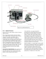
Configuration
Multiple
beam
control
units
can
be
provided,
allowing
1,
2
or
3
separate
electron
guns
to
be
independently
operated.
A
rear
panel
accessible
DIP
switch
configures
each
chassis
for
use
in
single
channel
or
multi
‐
channel
applications.
If
a
complete
system
is
ordered
from
the
factory,
this
configuration
setting
will
already
be
done.
If
you
are
reconfiguring
an
existing
system,
or
adding
a
beam
control
unit
in
the
field
the
details
of
the
configuration
process
are
outlined
below.


