EVA
Manual
23
118144
‐
001
REV.
A
Switch
Name
Programming
Feature
Switch
Position ON
Switch
Position OFF
1
RMT
CNTRL
Enables
remote
control
via
the
provided
Ethernet/RS
‐
232
interfaces.
ON(down)
for
RMT
CNTRL
OFF(up)
for
local
control
and
remote
analog
control
2
GUN2
Configures
the
Beam
Controller
chassis
as
GUN2.
Lights
up
the
front
panel
GUN2
lamp.
(See
Note
1)
ON(down)
for
GUN2
OFF(up)
for
Single
Gun
and
for
GUN1
and
GUN3
in
Multi
‐
Gun
configuration
3
GUN3
Configures
the
Beam
Controller
chassis
as
GUN3.
Lights
up
the
front
panel
GUN3
lamp.
(See
Note
1)
ON(down)
for
GUN3
OFF(up)
for
Single
Gun
and
for
GUN1
and
GUN2
in
Multi
‐
Gun
configuration
4
SINGLE
GUN
Selects
the
Emission
Current
feedback
signal
from
the
EVA
High
Voltage
Chassis.
For
single
gun
configuration
only.
ON(down)
No
GUN2
or
GUN3
installed
OFF(up)
for
Multi
‐
Gun
configuration
5
MULTI
‐
GUN
Selects
the
Emission
Current
feedback
signal
from
the
Gun
Output
Box
when
multiple
guns
are
installed.
ON(down)
on
GUN1,
GUN2,
GUN3
OFF(up)
for
Single
Gun
Configuration
6
n/u
7
n/u
8
n/u
Note1:
The
Beam
Controller
chassis
is
configured
as
GUN1
when
the
GUN2
and
GUN3
selector
switches
are
both
in
the
OFF
(up)
position.
The
GUN1
front
panel
lamp
will
illuminate.
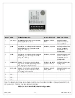
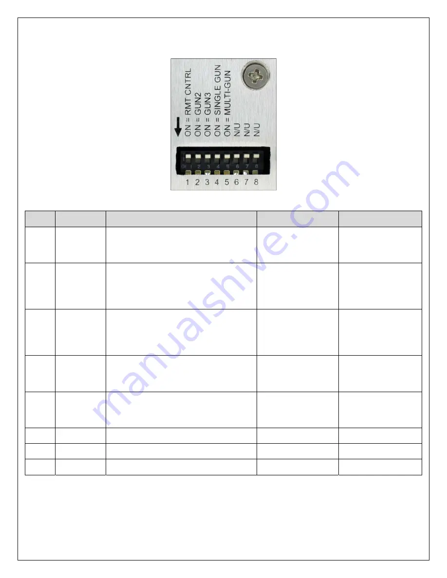
Table
6.1
Rear
Panel
DIP
Switch
Configuration


