81317-4r1 MXR20PN24 & MXR30PN24 Installation & User Guide
10 of 10
4
Operation of the HV Unit
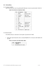
4.1 Analogue Interface
The MXR units with an analogue interface use the following control and monitor signals.
4.1.1 Analogue Control Inputs
Control
Assignment
Pin
Levels
Voltage Control
VSET
7
0V to 10V for 0 to 30kV [0
– 20kV], always positive
Rin
>1MΩ
Polarity change
(digital)
POL SET
8
TTL: Low = positive HV
High/open = negative HV
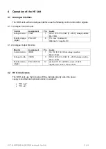
4.1.2 Analogue Output Monitors
Monitor
Assignment
Pin
Levels
Current monitor
IMON
1
0 to 10V for 0 to 500uA, always positive
Rout = 10kΩ
Voltage monitor
VMON
3
0V to 10V for 0 to 30kV [0
– 20kV] always positive
Rout = 10kΩ
Polarity monitor
(digital)
POL STATUS
12
positive HV: 0V (<200mV),
source 1.5kΩ
negative HV: +24V,
source 2.2kΩ
4.2 HV On Indicators
The MXR units use the following LEDs
to
indicate polarity when the power
supply is enabled and optional interlock is enabled:
•
“
HV +ve”
•
“HV -ve”


