PMX MANUAL
11
118164-001 REV. A
3.
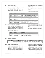
Connect HV cable to the CA3 type
high voltage output terminal at rear of
the unit.
4.
Connect the other side of HV cable
to the corresponding HV terminal on
tube housing.
5.
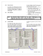
Connect the cable shield wire
accompanying HV cable to the PMX
ground stud and tube housing
separately.
2.5.2
Stator Cable Connection
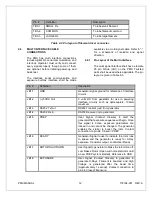
Refer to Table 2-1 for the X-Ray tube stator
connections.
1.
Tube low voltage cable is a hybrid
one with filament and stator drive
wire bundled together. Tube side
should be standard terminal style,
while generator side is unterminated.
Customer should terminate the wire
with suitable terminal.
2.
Connect wires from the X-Ray tube
housing low voltage connector stator
pins to PMX terminal block TB2
terminals 1 (stator PHASE), 2 (stator
RUN), 3 (stator COM), and 4
(GROUND).
3.
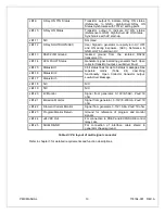
Connect tube thermal switch wires to
TB3-5 and TB3-6 if present. If not,
short the two pins. Normally, there
are no such separate wires for
MAMMO
tubes;
it is always
integrated into the three phase line.
Refer to tube housing data sheet for
specific information.
2.5.3
Filament Driver Cable Connection
1.
Filament driver cable has three wires
and bundled together with stator
wires within same cable. Customer
should terminate the wire with
suitable terminals and leave enough
length to reach the terminal TB3.
2.
Connect wires from the X-Ray tube
housing low voltage connector
filament pins to PMX terminal block
TB3 terminals 1 (FIL Small), 2 (FIL
COM), and 3 (FIL Large).


