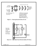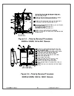
SL SERIES MANUAL
14
118006-001 REV T
+
1
2
3
4
5
6
7
Current
Monitor
M
M
Voltage
Monitor
+
TB1/J5
PS Common
Z out = 4.99k ohms +/-0.1%
Z out = 4.99k ohms +/-0.1%
It is recommended that analog signals be isolated via
isolation amplifiers. All cables should be shielded
with the shield being returned to the chassis ground
of the high voltage power supply.
Figure 3.3 -- Remote Monitor Test Point Designations
14
15
16
17
S1
S2
Remove jumper for remote
high voltage control
S1 = Remote High
S2 = Remote High
Voltage Off
Voltage On
All cables should be shielded
to the chassis ground of the
High Voltage Power Supply.
with the shields being returned
TB 1/J5
Momentary closure of S2 will enable HIGH
VOLTAGE ON.
S1 must be closed to enable HIGH VOLTAGE.
It is recommended to use relay contacts
for S1 and S2. Relays should be located
as close as possible to the high voltage
power supply. Coils should be driven
from isolated sources. Signals are at
15Vdc, 25mA max., and are only to be
used for contact closure.
Opening S1 will disable HIGH VOLTAGE ON and
switch the unit to the HIGH VOLTAGE OFF mode
.
Figure 3.4 Remote Control Of High Voltage On and High Voltage Off
Interface


