SL SERIES MANUAL
21
118006-001 REV T
Chapter 5
O
PTIONS
he options available for this power supply are
described in this section. Interface diagrams are
shown where required. Options are specified by
including the option code in the model number as
described in Section 1.5.
5.1 Adjustable
Overload Trip --AOL
The overload trip protection feature rapidly shuts down
the high voltage output when the current exceeds the limit
set by the current control dial on the front panel. A fast
acting circuit inhibits the generation of high voltage and
reverts the unit to POWER DOWN mode, illuminating
the OVER CURRENT indicator. When adjustable
overload trip is provided, it replaces the standard current
regulation feature.
5.2 220Vac Single Phase
Input--220
SL Series power supplies with the 220Vac input option
will operate from an input voltage of 220Vac RMS
±
10%, 50 to 60Hz, single phase.
5.3 No Slow Start--NSS
The no slow start option causes the output voltage of the
power supply to rise (within 50 msec) to the rated voltage
upon depressing the HIGH VOLTAGE ON switch.
5.4 Non-Standard Slow
Start--SS(x)
The non-standard slow start option allows the gradual rise
time of the output voltage to be different from the
standard of six seconds. To order the option place the
time desired in seconds after the suffix letter, i.e. SS (10)
denotes a 10 second rise time.
5.5 Extra Length Output
Cable--LL(ft)
Standard output cable is 10 feet of shielded high voltage
cable. Other lengths may be specified in multiples of 10
feet.
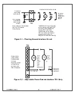
5.6 Floating Ground--FG
The floating ground option allows isolation of the power
supply common from the chassis ground. TB2 located on
the rear panel provides connection to the power supply
common circuit and to the chassis ground. This signal
can be used for a variety of applications. A typical
application for FG is for connection of an external meter
or circuit into the FG signal point. This circuit can
monitor actual current flow at a low voltage level. See
Figure 5.1 for typical connection to the floating ground
terminal.
NOTE:
On standard units, TB2-1 and TB2-2 are
connected to the chassis grounded internally. Maximum
floating ground voltage is 15V. Typically, the total
leakage current of the floating terminal to the chassis
terminal is less that 1
μ
A. It is important to realize there
are two separate components to this leakage current. The
first component is leakage current caused by the coupling
of the 60Hz line magnetics to the power supply circuitry.
This component can be measured when the power supply
is ON and in the HIGH VOLTAGE OFF mode. The
second component is the leakage current caused by the
coupling of the HVDC circuits to the chassis. The
component can be measured by first recording the leakage
current in the HV OFF mode, and then recording the
leakage at the desired HV setting. The difference
between the two values is the HVDC leakage current.
T


