SLM MANUAL
1
118073-001 Rev C
Chapter 1
I
NTRODUCTION
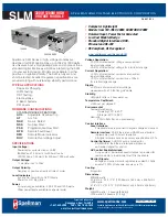
1.1 Description of the SLM Series
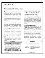
he SLM Series of high voltage generator modules are
designed for OEM applications up to 70kV and up to
1200watts. Its universal input, small package size and
choice of three standard digital interfaces simplifies
integrating the SLM into your system. DSP based control
circuitry provides excellent regulation, along with
outstanding stability performance. User programmable
firmware option makes the operation of the SLM flexible.
The dramatically reduced size of the SLM module,
compared to traditional high voltage modules, is obtained
by a state of the art off-line resonant converter. The
resonant converter utilizes a unique control scheme,
which allows constant frequency operation while
maintaining high efficiency. The high efficiency is
obtained by zero current switching (ZCS) resonant
control. High operating frequency, typically 50 kHz,
allows for low ripple and excellent dynamic response
capabilities.
The DC output voltage and current are controllable over
the full range of operation. Monitoring and control
signals are provided for simple, yet flexible control of the
power supply. The SLM series operates from 90 -
265Vac, at 50/60 Hz single phase for the 300Watt models
and 180–264Vac, at 50/60 Hz single phase for the
600Watt and 1200Watt models. The input is power
factor corrected and the SLM series operates at full power
continuous. The ambient temperature must be kept below
the maximum rating as specified in 1.2. The standard
warranty applies to the modules. Consult factory about
the warranty for custom SLM modules.
1.2 SLM Specifications
Input Voltage:
90-264Vac 47-63Hz, for 300watt models
180-264Vac 47-63Hz, for 600watt models
180-264Vac 47-63Hz, for 1200watt models
Power Factor:
FL:
≥
0.99
Output Voltage:
22 models: 1kv to 70kv
Voltage Regulation:
≤
0.01% of rated output voltage over specified input
voltage range
≤
0.01% of rated output voltage for a full load
change
Current Regulation:
≤
0.01% of rated output current over specified input
voltage range
≤
0.01% of rated output current for a ±100
μ
A for a
full voltage change
Ripple
:
≤
0.2% rms of maximum rated voltage,
measured with a 10 foot long HV cable
Polarity:
Positive or Negative polarity with respect
to ground. (Specify at time of ordering).
Stability:
≤
50ppm/hr after a 2 hour warm up
Temperature Coefficient
:
≤
100ppm /
C.
Temperature:
Operating: 0
C to 40
C
Storage: -40
C to +85
Humidity: 20% to 85% RH, non-condensing
.
Control Interface
Local Interface:
Voltage and current are externally
programmable over the entire range from zero to
maximum rating via 0-10VDC input.
+10Vdc Reference:
A +10Vdc reference is provided
for local programming via two potentiometers to be
used to adjust voltage and current.
Remote Interface:
USB, Ethernet and RS232 are
standard, implemented with 12 bits of resolution.
All digital monitors have an accuracy specification of
2%.
Control Software:
A VB GUI will be provided for
RS-232/USB, the Ethernet interface will have an
embedded applet for control.
Monitor Signals:
Voltage and current monitor signals are scaled 0-
10Vdc equals 0-100% of full scale. Accuracy is 1
%.
T
Summary of Contents for SLM SERIES
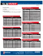
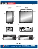
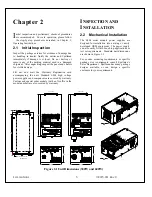
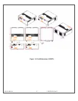
Page 15: ...SLM MANUAL 6 118073 001 Rev C Figure 2 2 Unit Dimensions 1200W ...
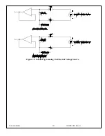
Page 19: ...SLM MANUAL 10 118073 001 Rev C Figure 3 3 Local Programming via External Voltage Source ...
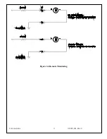
Page 20: ...SLM MANUAL 11 118073 001 Rev C Figure 3 4 Remote Monitoring ...
Page 40: ...Figure 9 Web Page 1 Contact Information 118080 001 REV A Page 13 of 95 ...
Page 98: ...Request Faults 68 20 ASCII 118080 001 REV A Page 71 of 95 ...


