SLM MANUAL
5
118073-001 Rev C
Chapter 2
I
NSPECTION AND
I
NSTALLATION
nitial inspection and preliminary checkout procedures
are recommended. For safe operation, please follow
the step-by-step procedures described in Chapter 3,
Operating Instructions.
2.1 Initial
Inspection
Inspect the package exterior for evidence of damage due
to handling in transit. Notify the carrier and Spellman
immediately if damage is evident. Do not destroy or
remove any of the packing material used in a damaged
shipment. After unpacking, inspect the panel and chassis
for visible damage.
Fill out and mail the Warranty Registration card
accompanying the unit. Standard SLM high voltage
power supplies and components are covered by warranty.
Custom and special order models (with an X suffix in the
model number) are also covered by warranty.
2.2 Mechanical Installation
The SLM series module power supplies are
designed for installation into existing or newly
developed OEM equipment. The power supply
can also easily fit into bench top applications or
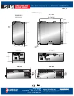
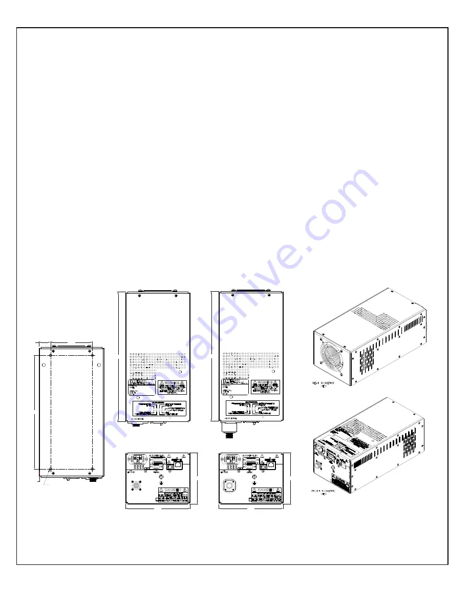
test set requirements. Standard unit dimensions
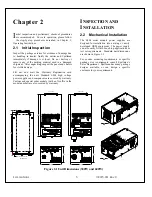
are shown in Figure 2.1
For custom mounting requirements or specific
package size requirements consult Spellman’s
Sales Department. Spellman has many package
designs available, or can design a specific
enclosure for your requirements.
BOTTOM VIEW
1KV - 50KV
60KV - 70KV
1.06
3.88
.75
10.50
4X 10-32 FEMALE THD
12.00
12.00
6.00
6.00
4.75
4.75
Figure 2.1 Unit Dimensions (300W and 600W)
I
Summary of Contents for SLM SERIES
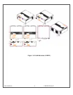
Page 15: ...SLM MANUAL 6 118073 001 Rev C Figure 2 2 Unit Dimensions 1200W ...
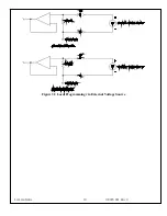
Page 19: ...SLM MANUAL 10 118073 001 Rev C Figure 3 3 Local Programming via External Voltage Source ...
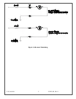
Page 20: ...SLM MANUAL 11 118073 001 Rev C Figure 3 4 Remote Monitoring ...
Page 40: ...Figure 9 Web Page 1 Contact Information 118080 001 REV A Page 13 of 95 ...
Page 98: ...Request Faults 68 20 ASCII 118080 001 REV A Page 71 of 95 ...


