UM8-40 MANUAL
11
118103-001 REV D
Chapter 5
O
PTIONS
5.1 L Option - Legacy Interface
The Legacy Interface provides form, fit and function
replacement for presently available commercially made
units.
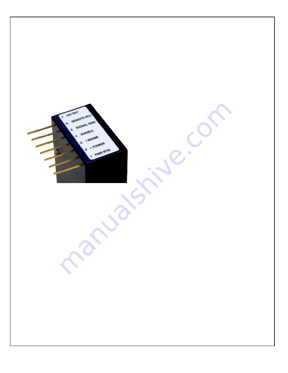
The standard UM8-40 is provided with a row of 13
interface pins on 0.1” center spacing. By removing “every
other pin” the Legacy Interface provides 7 pins on 0.2”
center spacing. Physically the UM8-40 with the Legacy
Interface will fit into printed circuit boards designed for
other commercially made units. A standard unit can be
turned into a Legacy Interface unit by clipping the
appropriate interface pins.
Functionality wise the Legacy Interface is electrically
identical to other commercially made units so interface
compliance is guaranteed.
5.2 C Option – Fast Rise Time
The C Option optimizes the UM8-40 for fast rise
time/low overshoot requirements. A Hysteretic control
circuit is employed providing improved performance. If
used for capacitor charging, a Spellman Capacitor
Charging Questionnaire should have been filled out to
assure all aspects of the intended usage were reviewed
assuring the appropriate unit was selected.
Typical rise times can be calculated using the following
formula:
t
RISETIME
= (V)(C + C
EXT
)/I
Where:
C =
Output Capacitance of Unit
C
EXT
= External Capacitance
I =
Nominal Output Current
V =
Maximum Rated Voltage
Where the minimum risetime shall never be less than
3ms.
Considering the maximum short circuit discharge rate is
important in fast rise time applications. Energy is stored
in the capacitance of the High Voltage Output Section of
the unit. Output limiting resistors located inside the unit
are electrically connected series with the output. These
resistors limit the short circuit discharge current to a safe
level. During short circuiting all the energy stored in the
High Voltage Output Section is dissipated as heat in the
output limiting resistors. If the repetitive short circuit
discharge rate is too great the internal limiting resistors
can get damaged due to thermal overload. Maximum
short circuit discharge rates can be calculated as follows:
(CV
2
)(f) < 1 watt
Where:
C =
Output Capacitance of Unit
V =
Rated Output Voltage of Unit
f =
Frequency of Discharge
5.3 T Option – Low Temperature
Coefficient
The T Option offers the UM8-40 with an improved
temperature coefficient. The standard voltage feedback
divider is replaced with one having a superior temperature
coefficient, resulting in a unit with 25ppm/C° (typical)
temperature coefficient.

