PAGE 3 OF 6
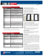
Standard Interface Connections
Fifteen (15) gold plated 0.025˝ (0.64mm) square
pins suitable for direct PCB mounting.
Legacy Interface Connections
Nine (9) gold plated 0.025˝ (0.64mm) square pins
suitable for direct PCB mounting.
Programming and Monitor Signals
Voltage and current programming is done via positive
polarity, high input impedance, 0 to 4.64Vdc signals.
Voltage and current monitors are positive polarity,
buffered low output impedance 0 to 4.64Vdc signals.
I Mon
The I Mon signal is a true output current monitoring
signal. All internal offsets due to feedback divider
currents have been compensated for.
Signature Resistor
A unique identifying signature resistor for each type
of unit is connected from Pin 1A to ground. Details if
desired are available upon request.
I Sense Signal
The polarity of the I Sense signal is opposite of the
polarity of the output voltage of the unit that generated
it. So a positive output polarity unit creates a negative
polarity current monitor signal; while a negative output
polarity unit creates a positive polarity current monitor-
ing signal. This signal is clamped to ground internally
via a bidirectional transient protection device and the
signal is made available via a series connected 47kΩ
isolation resistor. Internal HV dividers create a small,
linear offset voltage on this current monitor signal that
can be compensated for.
OT Output
The unit is protected by an internal thermostat that will
shut the unit off if the case temperature exceeds 65°C.
The OT Output signal will change states indicating an
over temperature fault has occurred. In order to clear the
OT signal and re-enable the unit, the temperature has to
drop below 55 degrees C and input power needs to be
recycled. For details on unit cooling requirements and the
OT Output signal please see the operator’s manual.
LEGACY INTERFACE (L OPTION)
PIN
SIGNAL
PARAMETERS
1
Power Ground Return
+12Vdc or +24Vdc power return
2
+ Power Input
+12Vdc or +24Vdc power input
3
I Sense
See I Sense text and tables for details
4
Enable Input
Low (<0.7V, Isink@1mA)=HV OFF,
High (open or >2V)=HV ON
5
Signal Ground
Signal Ground
6
Remote Adjust
Positive Polarity Unit:
0 to +4.64VDC = 0 to 100% rated voltage,
Zin >1M
Ω
Negative Polarity Unit:
+5VDC to 0.36V = 0 to 100% rated voltage,
Zin >100k
Ω
7
+5V Reference Output
+5Vdc ±1%, 25ppm/°C. Zout =475Ω
8
HV Ground Return
HV Ground Return
9
E Out Monitor
1000:1 ratio. Polarity of Voltage Monitor signal equals
polarity of unit. Accuracy is ±2%, 100ppm/°C. Calibrated
with DVM with 10MΩ input impedance
STANDARD INTERFACE
PIN SIGNAL
PARAMETERS
1
Power Ground Return
+12Vdc or +24Vdc power return/HV return
1A Signature Resistor
Unique Identifying resistor connected to ground
2
+ Power Input
+12Vdc or +24Vdc power input
2A OT Output
+5Vdc @ 1mA = Over Temp fault
3
I Sense
See I Sense text and tables for details
3A
I Mon
0 to 4.64Vdc = 0 to 100% rated output. Zout < 10kΩ
4
Enable Input
Low (<0.7V, Isink@1mA)=HV OFF,
High (open or >2V)=HV ON
4A
V Mon
0 to 4.64Vdc = 0 to 100% rated output. Zout < 10kΩ
5
Signal Ground
Signal Ground
5A I Pgm
0 to 4.64Vdc = 0 to 100% rated output. Zin > 47kΩ
Leave open for preset current limit @103% of rated output current
6
Remote Adjust
Positive Polarity Unit:
0 to +4.64VDC = 0 to 100% rated voltage,
Zin >1M
Ω
Negative Polarity Unit:
+5VDC to 0.36V = 0 to 100% rated voltage,
Zin >100k
Ω
Leave open if pin 6A (VPgm) is used for programming
6A V Pgm
0 to 4.64Vdc = 0 to 100% rated voltage. Zin > 100kΩ
Leave open if pin 6 (remote adjust) is used for programming
7
+5V Reference Output
+5Vdc ±1%, 25ppm/°C. Zout =475Ω
8
HV Ground Return
HV Ground Return
9
E Out Monitor
1000:1 ratio. Polarity of Voltage Monitor signal equals
polarity of unit. Accuracy is ±2%, 100ppm/°C. Calibrated
with DVM with 10MΩ input impedance
Power Ground Return, Signal Ground and HV Ground Return are connected
internally. For best performance they should not be connected externally.
Grayed out signals are provided for backward legacy compatability
and their use is not required.
Power Ground Return, Signal Ground and HV Ground Return are connected
internally. For best performance they should not be connected externally.
Standard Interface
Legacy Interface
SPELLMAN HIGH VOLTAGE ELECTRONICS CORPORATION
UM8-40
HIGH VOLTAGE
MODULE
See mechanical drawing for location and spacing details
Corporate Headquarters
Hauppauge, New York USA
+1-631-630-3000 FAX: +1-631-435-1620
e-mail: sales@spellmanhv.com
www.spellmanhv.com
128074-001 REV. K
Spellman High Voltage is an ISO 9001:2008 and ISO 14001:2004 registered company
Copyright © 2010 Spellman High Voltage Electronics Corp.

